
Method of wavelet coding a mesh object

An object and encoding technology, applied in image encoding, code conversion, image data processing, etc., can solve problems such as inability to perform adaptive decoding

Inactive Publication Date: 2004-09-01
FRANCE TELECOM SA
View PDF0 Cites 0 Cited by
  • Summary
  • Abstract
  • Description
  • Claims
  • Application Information

AI Technical Summary

Problems solved by technology

[0022] Thus, a disadvantage of these prior art methods is that, in order to perform adaptive decoding, the client must have an available display terminal with sufficient processing power to perform the decoding operation on the entire stream, select the correlation coefficients and from the coefficients thus selected reconstruct the image of the object
[0023] In other words, a disadvantage of these prior art methods is that a client with a display terminal with limited processing power cannot perform adaptive decoding

Method used


Image

  • Method of wavelet coding a mesh object
  • Method of wavelet coding a mesh object
  • Method of wavelet coding a mesh object

Examples


Embodiment Construction

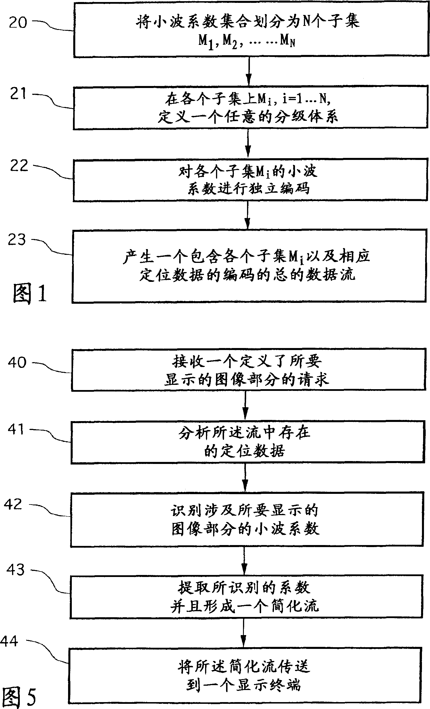
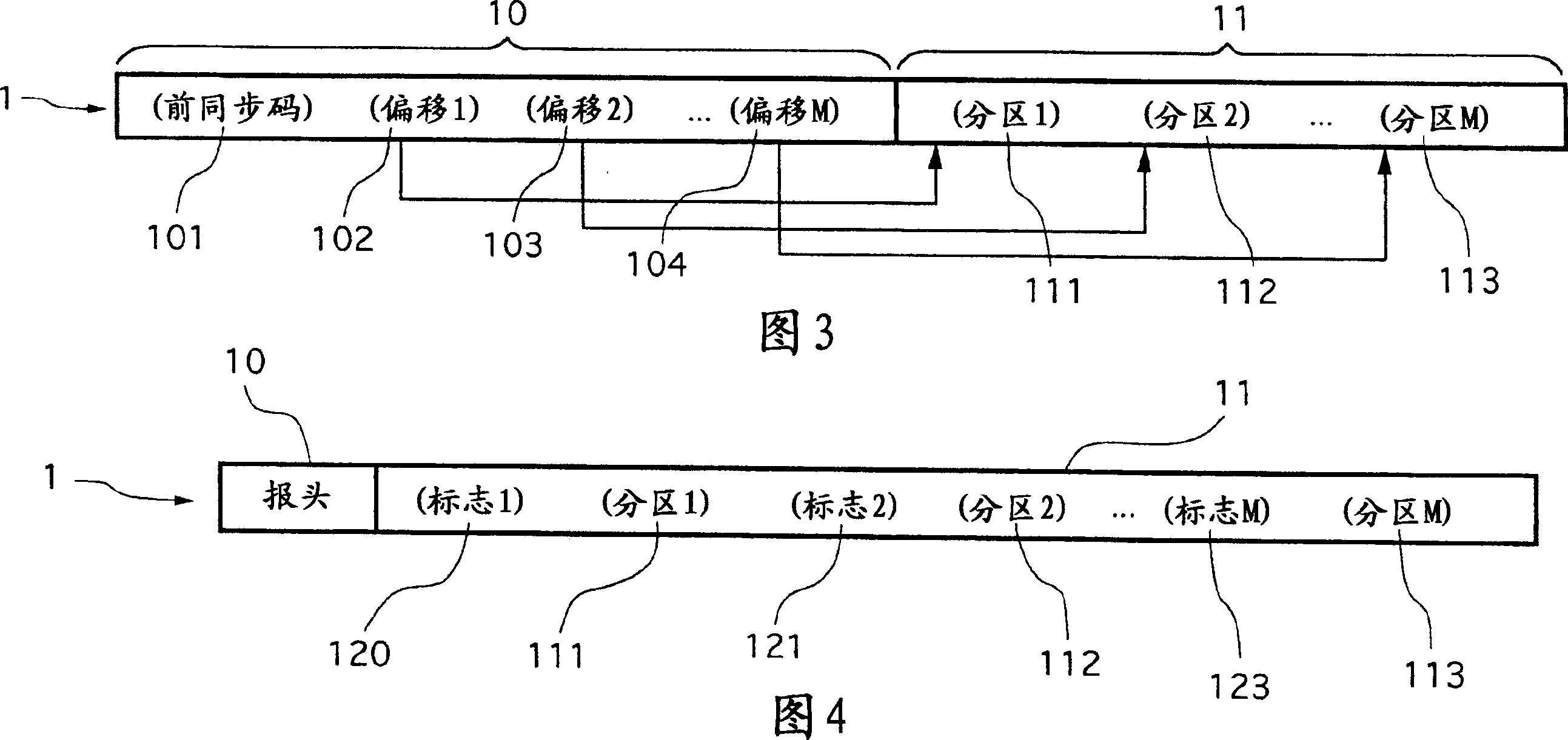
[0085]The general principle of the invention is based on inserting positioning data inside a data stream in order to be able to select coefficients and selectively transmit those coefficients as a function of the associated object area Generated when the meshed object is wavelet encoded.

[0086] Referring now to FIG. 1, there is shown a particular embodiment of the encoding method of the present invention.

[0087] Here we should consider the case where objects with at least two dimensions are encoded according to a method known as the "wavelet" method. It will be recalled that, according to this method, the object associated therewith has a base grid and wavelet coefficients corresponding to the refinement to be performed on said base grid in order to reconstruct the image of said object. Therefore, each node of the basic grid is associated with a wavelet coefficient.

[0088] It is assumed that the encoding device has performed the steps of constructing the basic grid and...


PUM


Abstract

The image encoding uses a base mesh and wavelet coefficients for local modifications of the mesh. Wavelet coefficients are partitioned into disjoint subsets each coded independently. Data permitting location of the wavelet coefficient relative to part of the image is inserted into the data used to reconstruct the image, to allow selective reconstruction of part of the image.

Description

technical field [0001] The field of the invention is the encoding of meshed objects having at least two dimensions. More specifically, the invention relates to the implementation of a method known as the "wavelet" method for displaying and encoding grids or gridded textures associated with graphical scene objects. The present invention is especially applicable to the second-generation wavelet, but is not limited to the second-generation wavelet. In 1998, Wim Sweldens published "The Lifting Scheme: A The second generation wavelets are introduced in the article "Construction of Second Generation Wavelets". [0002] The invention can be applied in all those fields where it is desired to optimize the storage and / or transmission of images. The invention is particularly, but not exclusively, applicable to storing and communicating 3D models, lifting grids, and objects and structures encoded by two-dimensional grids. Background technique [0003] It will be recalled that so-call...

Claims


Application Information

Patent Timeline
Patent Type & Authority Applications(China)
IPC IPC(8): G06T1/00G06T9/00H03M7/30H04N1/41H04N19/63
CPCG06T9/007H04N19/63
Inventor 帕特里克·吉欧亚
Owner FRANCE TELECOM SA
Learn More