Space correction method for 2D seisimc overlapping shift profile drawing

A profile and mapping technology, applied in seismology, seismic signal processing, geophysical surveying, etc., can solve problems such as low mapping accuracy, low work efficiency, and high labor intensity

Inactive Publication Date: 2004-08-04
DAQING PETROLEUM ADMINISTRATION
View PDF0 Cites 5 Cited by
  • Summary
  • Abstract
  • Description
  • Claims
  • Application Information

AI Technical Summary

Problems solved by technology

[0004] In order to overcome the problems of low mapping accuracy, high labor intensity, and low work efficiency of the existing two-dimensional seismic stack profile mapping and blank calibration method, the present invention provides a two-dimensional seismic stack profile blank calibration method, which The method is completed on the basis of seismic data processing and migration, which can improve the accuracy of deep structural map mapping, realize automatic computer empty calibration, reduce the labor intensity of interpreters, and improve work efficiency

Method used


Image

  • Space correction method for 2D seisimc overlapping shift profile drawing
  • Space correction method for 2D seisimc overlapping shift profile drawing
  • Space correction method for 2D seisimc overlapping shift profile drawing

Examples


Embodiment 1

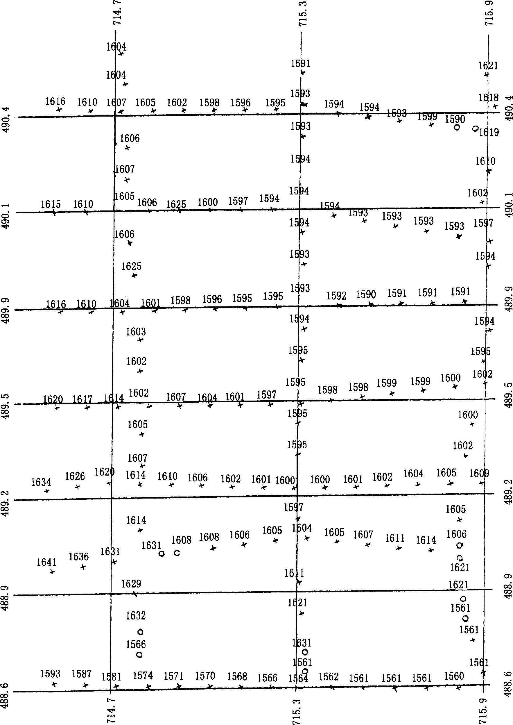
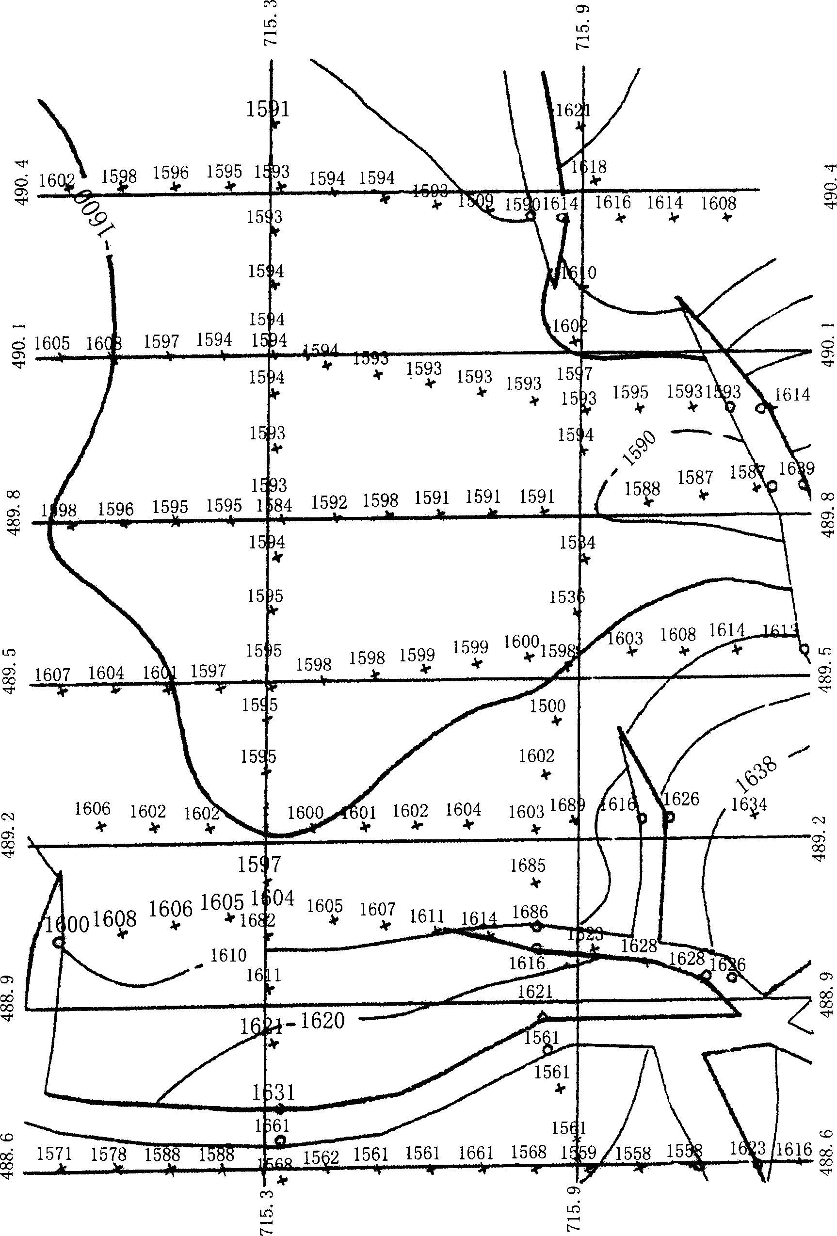
[0072] figure 2 Shifang 148 well area T 2 The depth value is projected onto the scatter diagram on the survey network after the blank calibration method of the two-dimensional seismic stack offset profile mapping method. "+" in the figure indicates the CDP point, and "°" indicates the breakpoint; , each CDP point has reached the real reflection point position underground after empty calibration; image 3 so figure 2 It is based on the depth structure map automatically generated after homing both the main survey line and the contact side line on the computer by this method. It takes less than 5 minutes to complete on the computer, but it takes several days to complete it by hand, which greatly improves the work efficiency and improves the accuracy of the structural diagram.

Embodiment 2

[0074] Figure 4 It is Songliao Xujiaweizi T 4 Layer t 0 scatterplot; Figure 5 It's Xujiaweizi T 4 The depth scatter diagram obtained after the layer is blank-calibrated by this method, "+" in the figure indicates the CDP point, and "°" indicates the break point. From Figure 4 and Figure 5 can be found in Figure 5 The empty calibration direction of each CDP point is homing along the updip direction of the formation. According to the migration principle, after homing, each CDP point has reached the real reflection point position underground.

[0075] It can be seen that the 2D seismic stack deflection section drawing blank correction method uses the data of the main survey line and the contact survey line to make the structural map at the same time, without loss of data points; the true depth structural map is drawn, and the structural shape is real. The position of the high point is accurate; using computer automatic empty calibration, the labor intensity of the int...


PUM


Abstract

A space correction method for 2D seismic overlapping shift profile drawing includes such steps as choosing a reflection interface of underground object layer, taking a CDP point on the interface, drawing a normal plane perpendicular to the interface by a measuring line and said CDP point, drawing another normal plane by another measuring line and said CDP point, intersecting between said two normal planes, and deriving and calculating the vertical distance from the CDP point to ground surface and the distance from the point of the CDP point reflected from two normal plant to ground surface and the real position of the CDP point on ground surface. Its advantages are high efficiency and high precision.

Description

Technical field: [0001] The invention relates to a method for interpreting seismic data in petroleum seismic exploration, and belongs to a method for forming and correcting two-dimensional seismic stacked deviation profiles. Background technique: [0002] In recent years, two-dimensional seismic stacking sections have been widely used in production, and the accuracy of fault interpretation has been guaranteed, so that the accuracy of structural maps has been significantly improved compared to before. However, the two-dimensional seismic stack deflection section only resets the seismic reflection wave along the direction of the two-dimensional survey line, only along the direction of the two-dimensional survey line, but does not make a blank correction in the direction of the vertical survey line. The dimensional stacked partial profile is still the normal plane, and the T read at the intersection of the two measuring lines 0 The time is not equal and cannot be closed, which...

Claims


Application Information

Patent Timeline
Patent Type & Authority Applications(China)
IPC IPC(8): G01V1/00G01V1/28
Inventor 王世清
Owner DAQING PETROLEUM ADMINISTRATION
Why Eureka
Try Eureka