On-Board holder

A vehicle and bracket technology, which is applied to vehicle parts, transportation and packaging, telephone structure, etc., can solve problems such as plating detachment, plug end deformation, fracture, etc., and achieve the effect of meeting the position requirements

Inactive Publication Date: 2004-06-30
PANASONIC CORP
View PDF0 Cites 3 Cited by
  • Summary
  • Abstract
  • Description
  • Claims
  • Application Information

AI Technical Summary

Problems solved by technology

[0004] However, since the connecting plug 102 protrudes from the housing 103 and the end of the connecting plug is plated as described above, when the cellular phone 101 is placed on the cradle, the housing of the cellular phone 101 and the connecting plug Therefore, if the cellular phone 101 is placed on the holder many times, its plating may come off or the end of the plug may be deformed or broken.

Method used


Image

  • On-Board holder
  • On-Board holder
  • On-Board holder

Examples


Embodiment Construction

[0020] Referring to the accompanying drawings, the bracket installed on the vehicle in the preferred embodiment of the present invention will be described in detail.

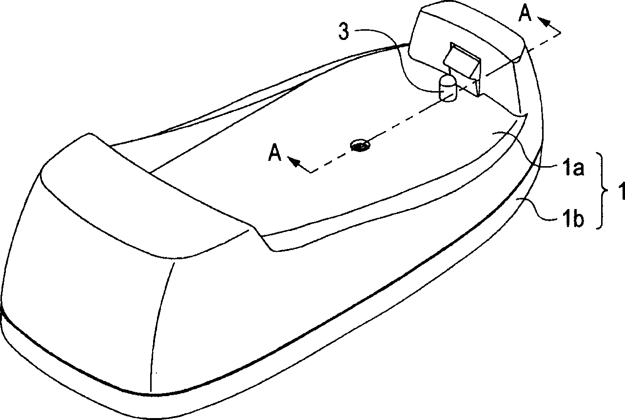
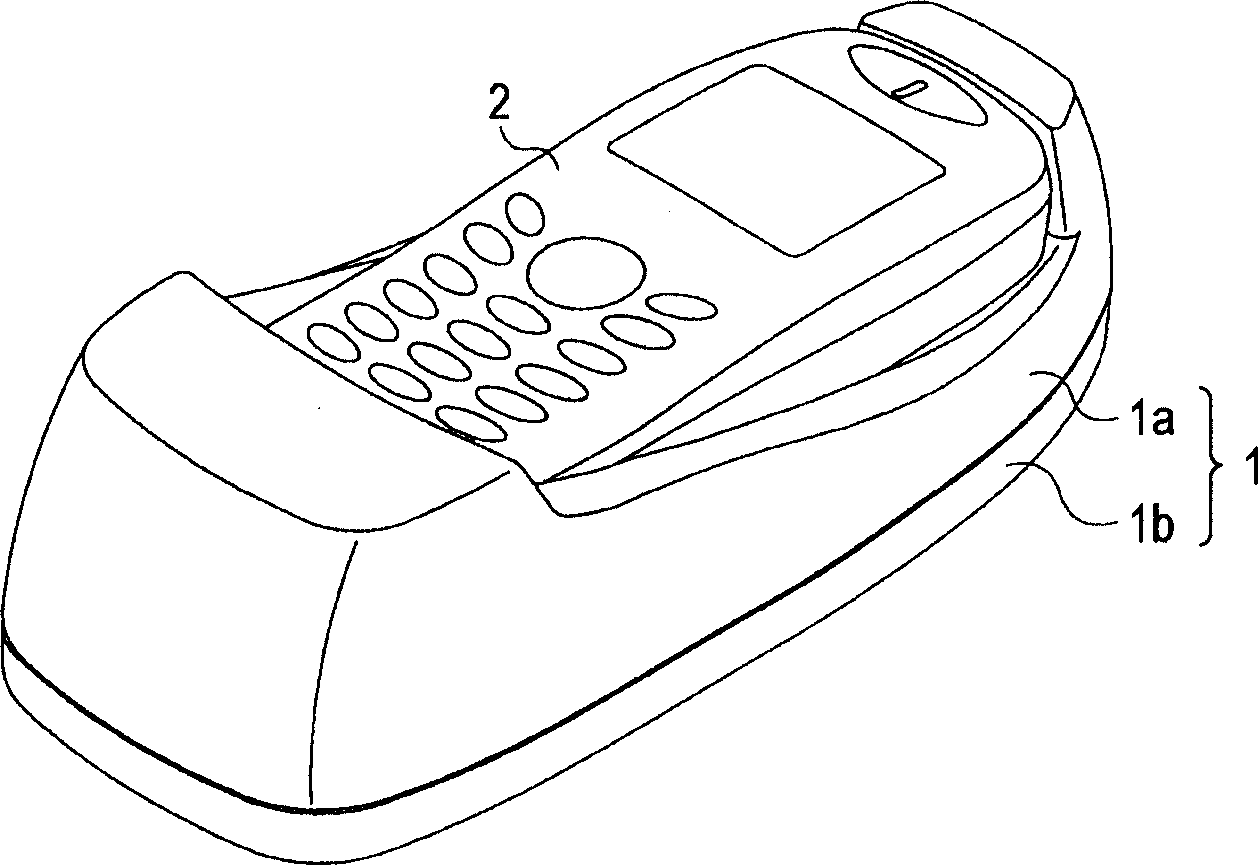
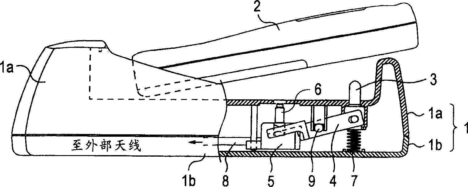
[0021] figure 1 is a perspective view of a bracket mounted to a vehicle according to an embodiment of the present invention. figure 2 is a perspective view of a cradle mounted to a vehicle according to an embodiment of the present invention, in which a cellular phone has been placed. Figure 3 is along the figure 1 The side view and cross-sectional view of the bracket installed on the vehicle on the line A-A in (a) shows that the mobile phone will be placed on the bracket, and (b) shows that the mobile phone has been placed on the bracket. Figure 4 is an exploded perspective view of a bracket mounted to a vehicle according to an embodiment of the present invention.

[0022] Such as figure 1 As shown in FIG. 3, a bracket mounted to a vehicle according to an embodiment of the present invention is used to plac...


PUM


Abstract

A holder arranged such that the position of a connection plug is not limited and the connection plug does not touch an electronic apparatus a portable telephone; when the electronic apparatus is set. U nder a state where the portable telephone is not set in the one board holder, a pin projects from the setting face of an upper case. The pin is pushed down into a case, when the portable telephone is set. A guide can turn about a post and oscillates clockwise when the pin is pushed dwn to push up a plug holder fixed to the other end of the guide. A connection plug is fixed to the plug holder. When the pin is pushed down by setting the portable telephone and the plug holder is pushed up by the guide the connection plug projects from an upper case. When the connection plug projects to enter a hole made in the back face of the portable telephone forward end of the connection plug touches a connector provided at the end of the hole.

Description

technical field [0001] The present invention relates to a cradle for a mobile phone mounted on a vehicle. Background technique [0002] A conventional cradle installed on a vehicle with a mobile phone placed thereon is shown in FIG. 5 . Figure 5 is a side view and a cross-sectional view of a conventional bracket mounted on a vehicle, wherein the portable phone 101 in Figure 5(a) is in a state to be placed on the bracket, and the portable phone 101 in Figure 5(b) It is in the state of having been placed on the bracket. As shown in FIG. 5, the connection plug 102 is arranged inside the housing wall surrounding the portable phone 101, which is placed on a conventional cradle for connection to a vehicle. A connection plug 102 protrudes from the housing 103 and is connected to a cable 104 in the housing 102 that is connected to an external antenna. [0003] A hole (not shown in the figure) is provided on the back of the cellular phone 101, into which the connection plug 102 is...

Claims


Application Information

Patent Timeline
Patent Type & Authority Applications(China)
IPC IPC(8): B60R11/02H04M1/04H04M1/11
CPCB60R11/0241H04M1/04
Inventor 泉田芳宏饭田忍
Owner PANASONIC CORP
Why Eureka
Try Eureka