
Switch power source device

A technology of switching power supply and switching elements, which is applied in the direction of circuit devices, emergency protection circuit devices, emergency protection devices with automatic disconnection, etc., and can solve problems such as cost increase and circuit complexity

Inactive Publication Date: 2004-06-23
SHARP KK
View PDF0 Cites 7 Cited by
  • Summary
  • Abstract
  • Description
  • Claims
  • Application Information

AI Technical Summary

Problems solved by technology

Therefore, it also complicates the circuit, which is a major cause of cost increase.

Method used


Image

  • Switch power source device
  • Switch power source device
  • Switch power source device

Examples


Embodiment Construction

[0032] An embodiment of the present invention will be described.

[0033] The switching power supply device (the present power supply device) according to this embodiment is a device for supplying the respective required constant voltages V01 and V02 to the above-mentioned plurality of sets of loads 11 and 12 .

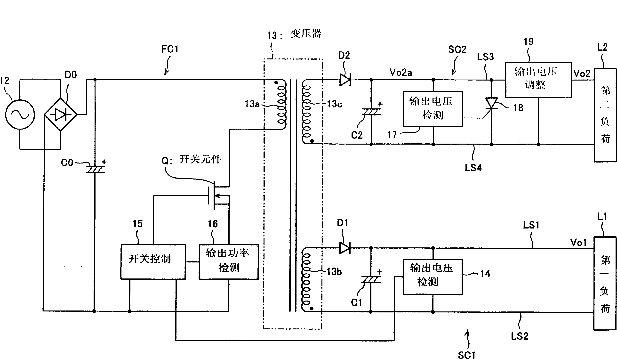
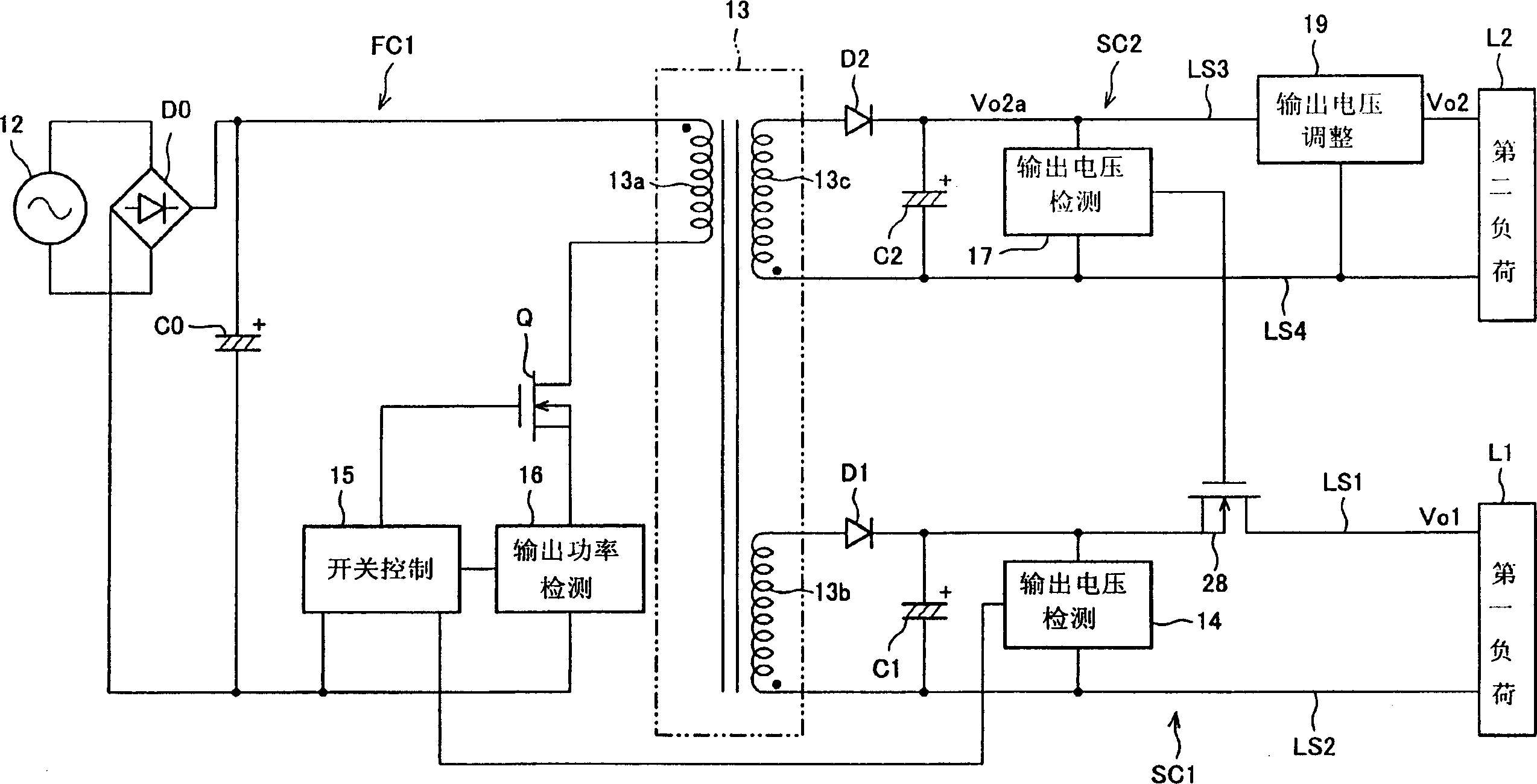
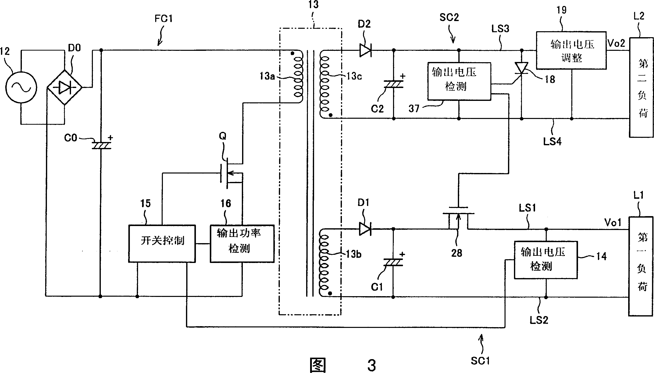
[0034] figure 1 It is a block diagram showing the electrical configuration of this power supply unit. As shown in the figure, this power supply device has a configuration including primary circuit FC1 of transformer 13 and two secondary circuits SC1 and SC2 of transformer 13 (first secondary circuit SC1 and second secondary circuit SC2).

[0035] Also, the present power supply device is modified so that relatively low (low consumption) electric power (first electric power) having a relatively low voltage V01 is supplied to the first load 11 of the first secondary circuit SC1. On the other hand, relatively high (high consumption) electric power (second electric powe...


PUM


Abstract

The switched-mode power supply includes an output value sensor circuit measuring a current flow through a switching device and a switching control circuit implementing overcurrent protection. Also included in the power supply are: a second output voltage sensor circuit detecting a high output voltage Vo2 for the second load; and a short-circuit device 18 quasi-shorting the terminals of the second load when the detected value of the voltage is more than or equal to a specific value. Therefore, if the short-circuit device 18 shorts out, the secondary load increases, and the output for the relatively low load L1 can be restrained by overcurrent protection. Thus, a reliable overcurrent protection can be achieved using a simple construction by means of cross-regulation, without a complex arrangement where a separate current sensor circuit is provided to each output of the secondaries to terminate or control the outputs independently from each other based on the detected current values.

Description

field of invention [0001] The present invention relates to a switching power supply device, and particularly to a switching power supply device including multiple sets of secondary side circuits. Background technique [0002] Image 6 A block diagram showing the electrical structure of a typical prior art switching power supply device 1 is shown. This power supply device 1 supplies constant output voltages V01 and V02 required by each of the above-mentioned multiple sets of loads 11 and 12 . [0003] As shown in the figure, the power supply device 1 receives an AC voltage (AC power) from a commercial power supply 2 to an AC input unit. Then, the AC voltage is converted into a DC voltage by a rectifier diode d0 and a smoothing capacitor C0, and used as a power source of the power supply device 1 itself (a DC power source such as a battery may also be used as a power source). [0004] In addition, if Image 6 In the device 1 shown, a series circuit consisting of a switching ...

Claims


Application Information

Patent Timeline
Patent Type & Authority Applications(China)
IPC IPC(8): H02M3/28H02H3/02H02H7/12H02M3/335
CPCY10T307/469Y10T307/406H02H3/023H02M3/33561H02H7/1213
Inventor 岩下安广
Owner SHARP KK
Learn More