Driving Speed-changing device

A technology of speed change mechanism and transmission parts, applied in transmission devices, friction transmission devices, mechanical equipment, etc., can solve the problems of short service life, high noise, easy wear and so on

Inactive Publication Date: 2004-06-16
何仁志
View PDF0 Cites 2 Cited by
  • Summary
  • Abstract
  • Description
  • Claims
  • Application Information

AI Technical Summary

Problems solved by technology

However, there are disadvantages such as large volume and large speed ratio error in the speed change of the pulley; the worm gear is usually used in the occasion of changing the transmission direction, the structure is complicated, and the processing cost is high; the speed ratio of the roller speed change is effective and is rarely used; The most widely used is the gear transmission speed change, and its disadvantages are that the structure is complex, the processing cost is high, the noise is large, it is easy to wear, the service life is short, and maintenance is troublesome.

Method used


Image

  • Driving Speed-changing device
  • Driving Speed-changing device
  • Driving Speed-changing device

Examples


Embodiment Construction

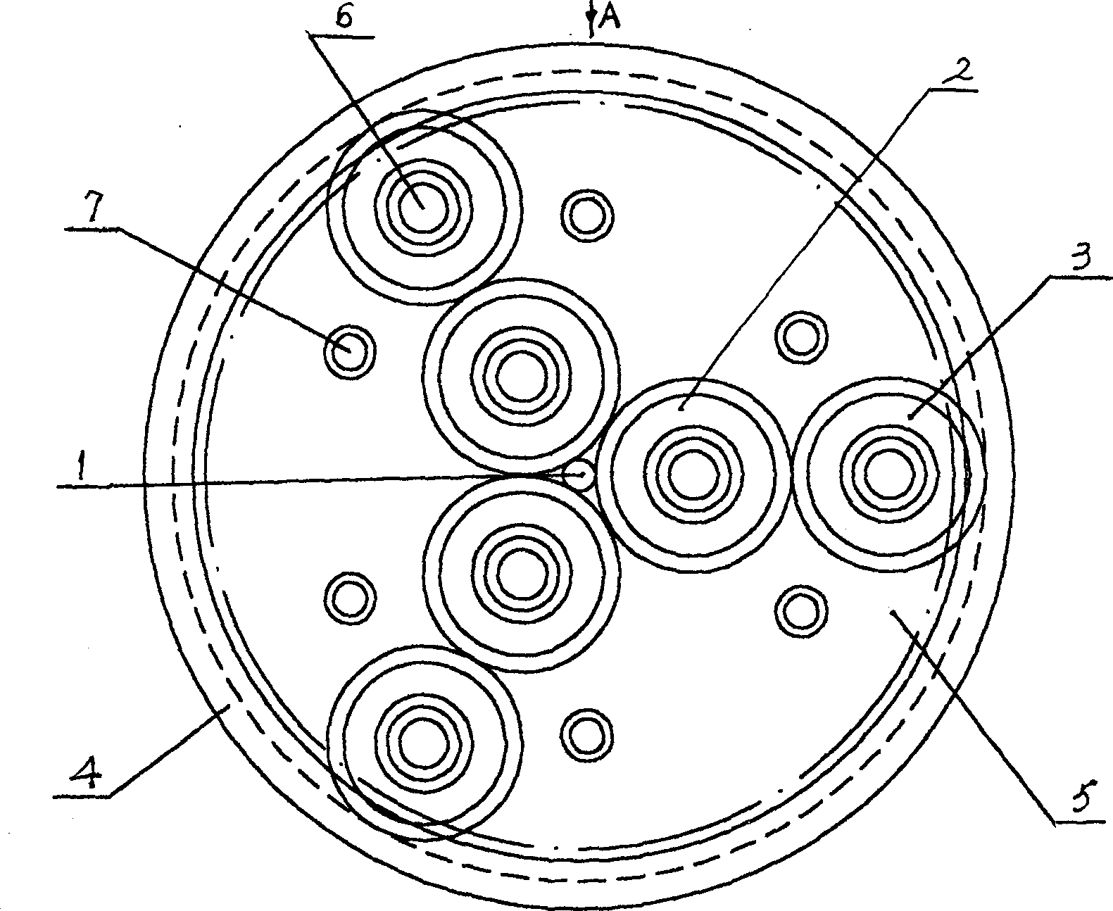
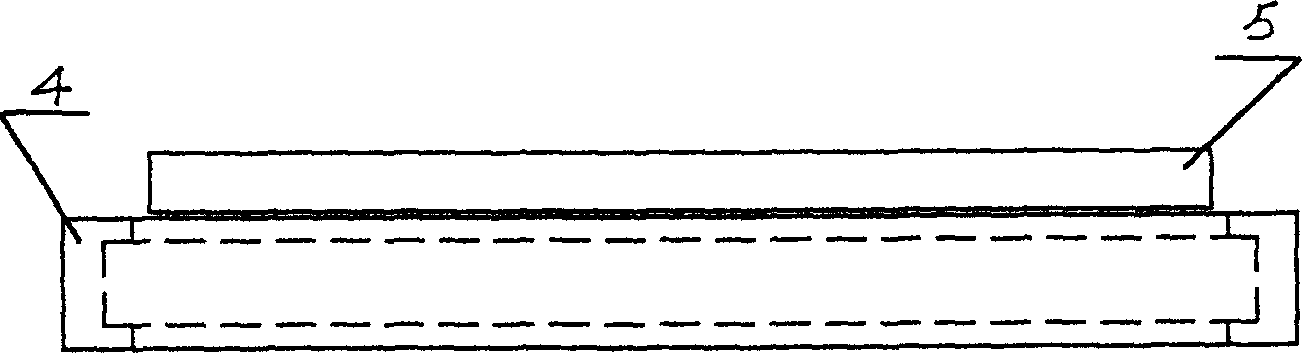
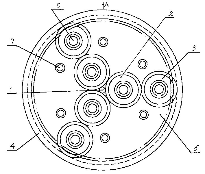
[0006] The invention discloses a transmission and speed change mechanism, which is composed of a drive shaft (drive shaft) driven by power (mainly driven by a motor) and a transmission component matched with the drive shaft. The main feature is that the bearing is used as the transmission component. Bearing pin 6 is installed on the support 5, and support 5 has the fixing screw hole 7 that connects in addition, and the outer side of bearing matches with bearing sleeve 4, and bearing sleeve 4 is connected with working equipment. The drive shaft 1 is in friction fit with two evenly distributed bearings or three bearings 2, the best example is figure 1 Shown are three bearings, and the outer ring bearing 3 can be matched with the inner ring bearing 2 directly matched with the drive shaft 1, and the outer ring bearing 3 and the bearing sleeve 4 are frictionally matched, and the inner and outer ring bearings 2, 3 is installed on the bracket 5.

[0007] The transmission speed chang...


PUM


Abstract

The invention relates to a transmission speed-change unit, which comprises a power driven shaft and a transmission component engaging the drive shaft, wherein the transmission component is a bearing mounted on the supporting frame, the outboard of the bearing co-operates the bearing sleeve by friction, the bearing sleeve is connected with the working device. The advantages of the invention are low noise of bearing transmission, better abrasion-resistance, and longer service life.

Description

technical field [0001] The invention relates to a transmission speed change mechanism, which can be widely used in related industries such as motors and machinery. Background technique [0002] There are many types of structures that use mechanical transmission to change the speed ratio. The most commonly used ones are gear transmission, worm gear, pulley, and roller. However, there are disadvantages such as large volume and large speed ratio error in the speed change of the pulley; the worm gear is usually used in the occasion of changing the transmission direction, the structure is complicated, and the processing cost is high; the speed ratio of the roller speed change is effective and seldom used; The most widely used is the gear transmission speed change, and its existing defects are that the structure is relatively complicated, the processing cost is high, the noise is large, it is easy to wear, the service life is short, and maintenance is troub...

Claims


Application Information

Patent Timeline
IPC IPC(8): F16H13/00
Inventor 钟先成
Owner 何仁志
Why Eureka
Try Eureka