
High power microwave plasma torch

A microwave plasma, high-power technology, applied in the field of ion torch, can solve the problems of inconvenient adjustment, low power level, complex excitation and maintenance mechanism, etc., and achieve the effect of simple mechanism, large incident power and convenient adjustment

Inactive Publication Date: 2004-06-09
INST OF METAL RESEARCH - CHINESE ACAD OF SCI
View PDF0 Cites 18 Cited by
  • Summary
  • Abstract
  • Description
  • Claims
  • Application Information

AI Technical Summary

Problems solved by technology

[0004] The purpose of the present invention is to provide a high-power microwave plasma torch that can solve the problems of complex excitation and maintenance mechanism, inconvenient adjustment, and low power level.

Method used

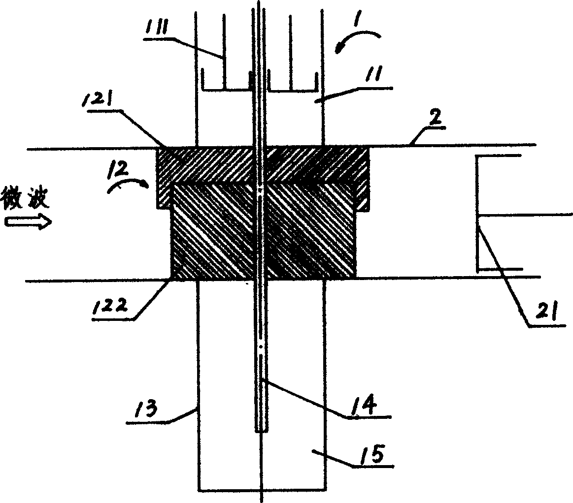
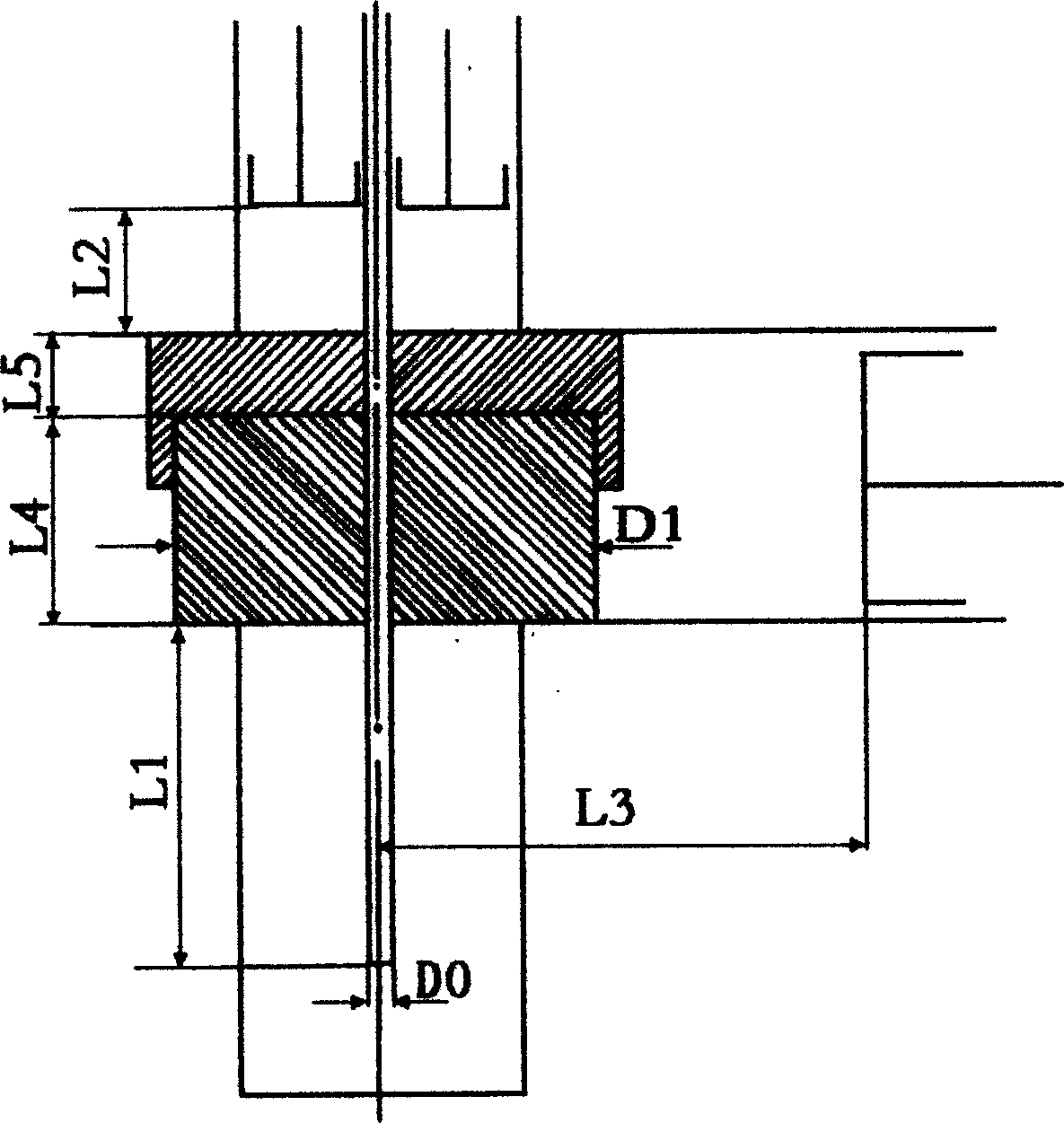
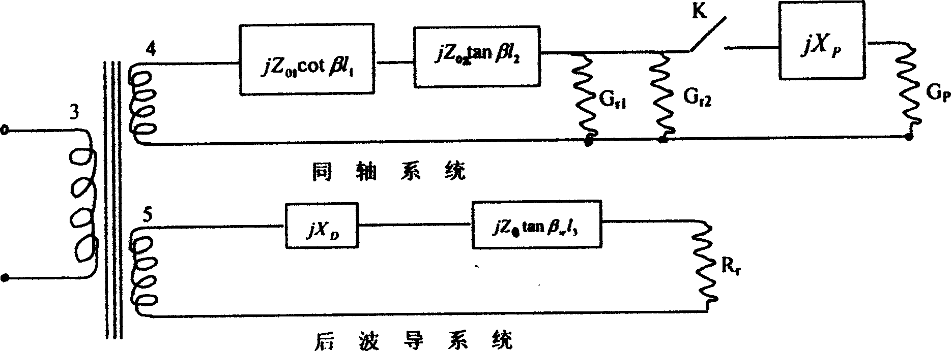

Image

  • High power microwave plasma torch
  • High power microwave plasma torch
  • High power microwave plasma torch

Examples


Embodiment Construction

[0020] The present invention relates to a high-power, high-efficiency microwave plasma excitation device, figure 1It is a structural schematic diagram of the device, including a tunable coaxial resonant cavity 1, a rectangular waveguide 2, and a waveguide / coaxial conversion device 12 is arranged inside the rectangular waveguide 2, and the waveguide / coaxial conversion device 12 is a door twist block 121 and The door twist structure of the dielectric single wire 122 buckled up and down, the waveguide / coaxial conversion device 12 is closely connected with the upper and lower surfaces of the rectangular waveguide 2, and the tunable coaxial resonant cavity 1 is located on the upper and lower sides of the waveguide 2 and connected to the The coaxial upper cavity 11, the lower cavity 15, and the waveguide / coaxial conversion device 12 are jointly formed by the coaxial / coaxial conversion device 12. The upper and lower chambers are coaxial lines formed by the outer conductor 13 and the i...


PUM


Abstract

A large power microwave plasma torch includes a tuned coaxial resonator, a rectangular waveguide with a wavequide / coaxial converting device to be structure blocked up and down by a door-knob block a door-knob structure locked up and down by a door-knob block and a medium line and con closely with top bottom surfaces of the rectangular wavequide, the said resonator is composed of an top and bottom cavities coaxial with the converter and placed at either side of the waveguide and the converter, one end of the inner conductor is plug in the low cavity, the other end passes through the medium single line, door-knob block and the up cavity, a resonator sort circuit piston is set along the axial line between inner and outer conductors, one end of the waveguide is set with a micro wave source and a waveguid a microwave source and a waveguide shout circuit piston at the other.

Description

technical field [0001] The invention relates to the field of plasma torches, in particular to a high-power microwave plasma torch. Background technique [0002] According to the method of excitation, plasma can be divided into conventional DC (AC) plasma, high frequency or radio frequency plasma, microwave induced plasma, laser plasma and thermally excited plasma. Plasma technology has been widely used in the preparation and processing of materials, thermonuclear reactions, and the treatment of toxic and hazardous waste. Conventional DC (AC) plasma is excited by forming a strong electric field strength (3000V / mm for air) between a pair of electrodes to break down the gas. In practical applications, conventional DC (AC) plasma has the disadvantages of short electrode life and electrode contamination due to high-temperature vaporization of the electrode. Although the electrode life can be improved by forced water cooling (currently reaching hundreds of hours), the applicatio...

Claims


Application Information

Patent Timeline
Patent Type & Authority Applications(China)
IPC IPC(8): H05H1/46
Inventor 杨永进张劲松徐兴祥
Owner INST OF METAL RESEARCH - CHINESE ACAD OF SCI
Learn More