
Length sensor

A technology of length measurement and measuring head, which is applied in the direction of measuring devices, mechanical measuring devices, measuring gauges, etc., and can solve problems such as measuring head friction and lateral bending

Inactive Publication Date: 2004-06-02
DR JOHANNES HEIDENHAIN GMBH
View PDF2 Cites 4 Cited by
  • Summary
  • Abstract
  • Description
  • Claims
  • Application Information

AI Technical Summary

Problems solved by technology

The helical spring is placed in a hole in the measuring head, which limits a relatively thick measuring head
For the required large strokes of the measuring head and the application of long helical springs, there is also the problem of lateral bending here, which causes friction between the helical spring and the measuring head

Method used


Image

  • Length sensor
  • Length sensor
  • Length sensor

Examples


Embodiment Construction

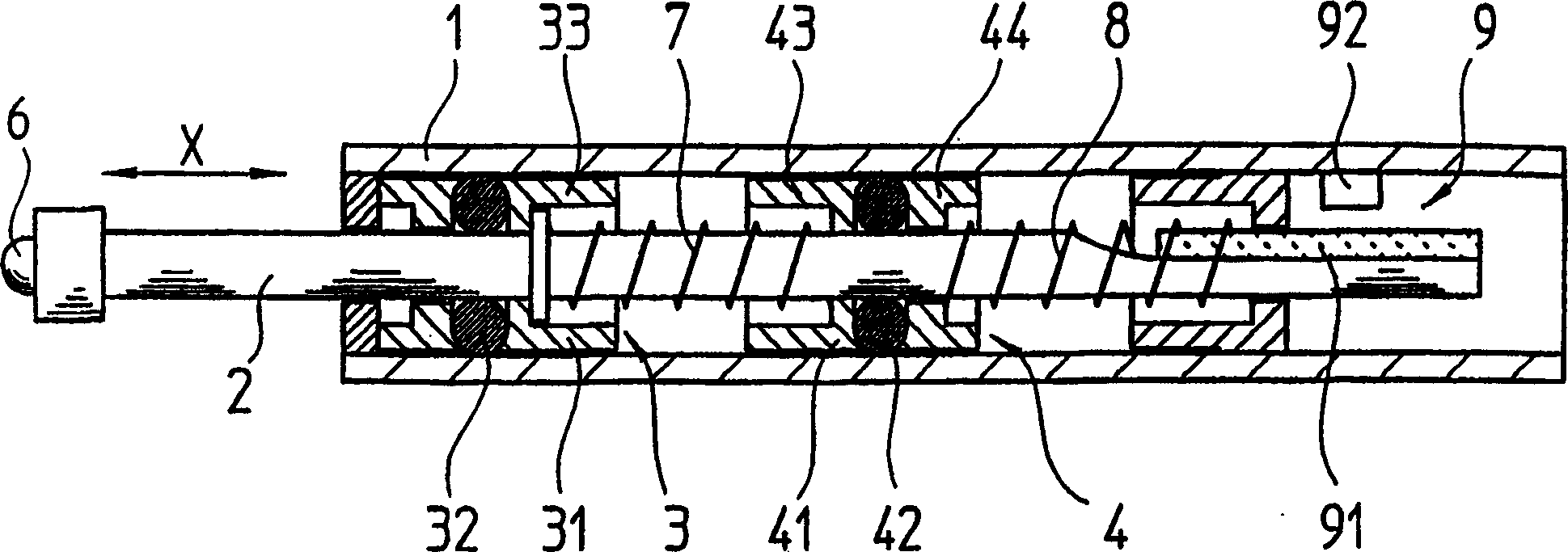
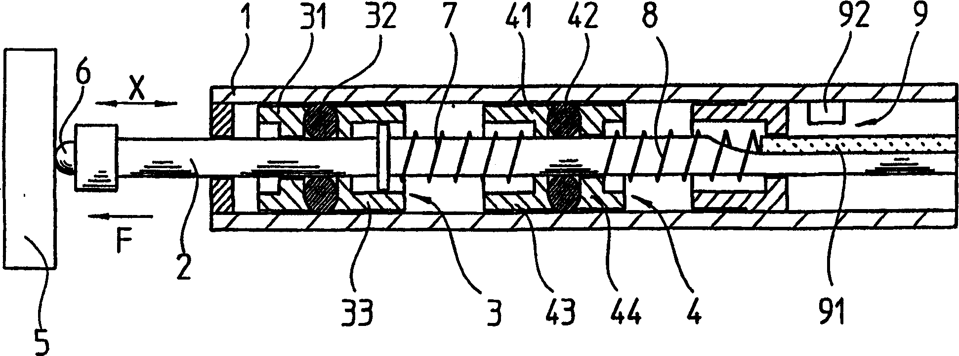
[0016] according to figure 1 with figure 2 An embodiment of a length measuring device designed according to the present invention is described below. The figures schematically show a cross-sectional view of the entire length measuring device, which comprises a base body 1 in which a rod-shaped measuring head 2 is supported, which is slidable in the measuring direction X. FIG.

[0017] Measure a figure 2 In the workpiece 5 shown, the end of the measuring head 2 is designed as a spherical abutment 6 . During a contact process, the measuring head 2 is pressed with the contact part 6 with a force F against the surface to be measured of the workpiece 5 . This force F is generated by helical springs 7 and 8 , which are arranged one behind the other in the measuring direction X and press the abutment 6 against the workpiece 5 . For compact construction, the turns of the helical springs 7 , 8 extend around the circumference of the circular measuring head 2 . In order to avoid f...


PUM


Abstract

The probe has a probe pin (2) with a probe element (6) for scanning an object (5) by moving relative to a base body (1) against a spring force. The probe pin is biased in the measuring direction (X) by several spring elements (7,8). A guide element (4) is provided between each two spring elements. The guide element is displaceably mounted on the probe pin and on the base body.

Description

technical field [0001] The invention relates to a length measuring device according to the preamble of claim 1 . Background technique [0002] This length measuring device is used for measuring workpieces in manufacturing process technology. For example, thickness, width, depth, length and inner or outer diameter can be ascertained. [0003] US 5,072,174 describes a length measuring device having the features stated in the preamble of the claims, in which the measuring head is slidably supported in the longitudinal direction in a basic body by means of a guide in the form of a ball guide. The contact pressure required to engage the workpiece to be measured is generated by a helical spring, which is fixed at one end to the measuring head and at the other end to the base body. [0004] The length of the coil spring must be at least equal to the probe travel, but long coil springs have a tendency to bend sideways. The greater the desired stroke of the measuring head, the lon...

Claims


Application Information

Patent Timeline
Patent Type & Authority Applications(China)
IPC IPC(8): G01B5/02G01B3/00G01B3/22G01B11/00G01B21/00
CPCG01B3/002G01B3/22G01B3/008G01B11/00
Inventor P·赫尔克特L·贝格
Owner DR JOHANNES HEIDENHAIN GMBH
Learn More