
Impedance calibrating circuit

A technology for calibrating circuits and impedance matching circuits, applied in logic circuits, line impedance variation compensation, input/output impedance improvement, etc., and can solve problems such as signal reflection noise aggravation

Inactive Publication Date: 2004-05-26
TEXAS INSTR INC
View PDF1 Cites 11 Cited by
  • Summary
  • Abstract
  • Description
  • Claims
  • Application Information

AI Technical Summary

Problems solved by technology

The signal reflection noise problem is further exacerbated by the smaller amplitude of the transmitted signal compared to parallel ATA transmission

Method used


Image

  • Impedance calibrating circuit
  • Impedance calibrating circuit
  • Impedance calibrating circuit

Examples


Embodiment Construction

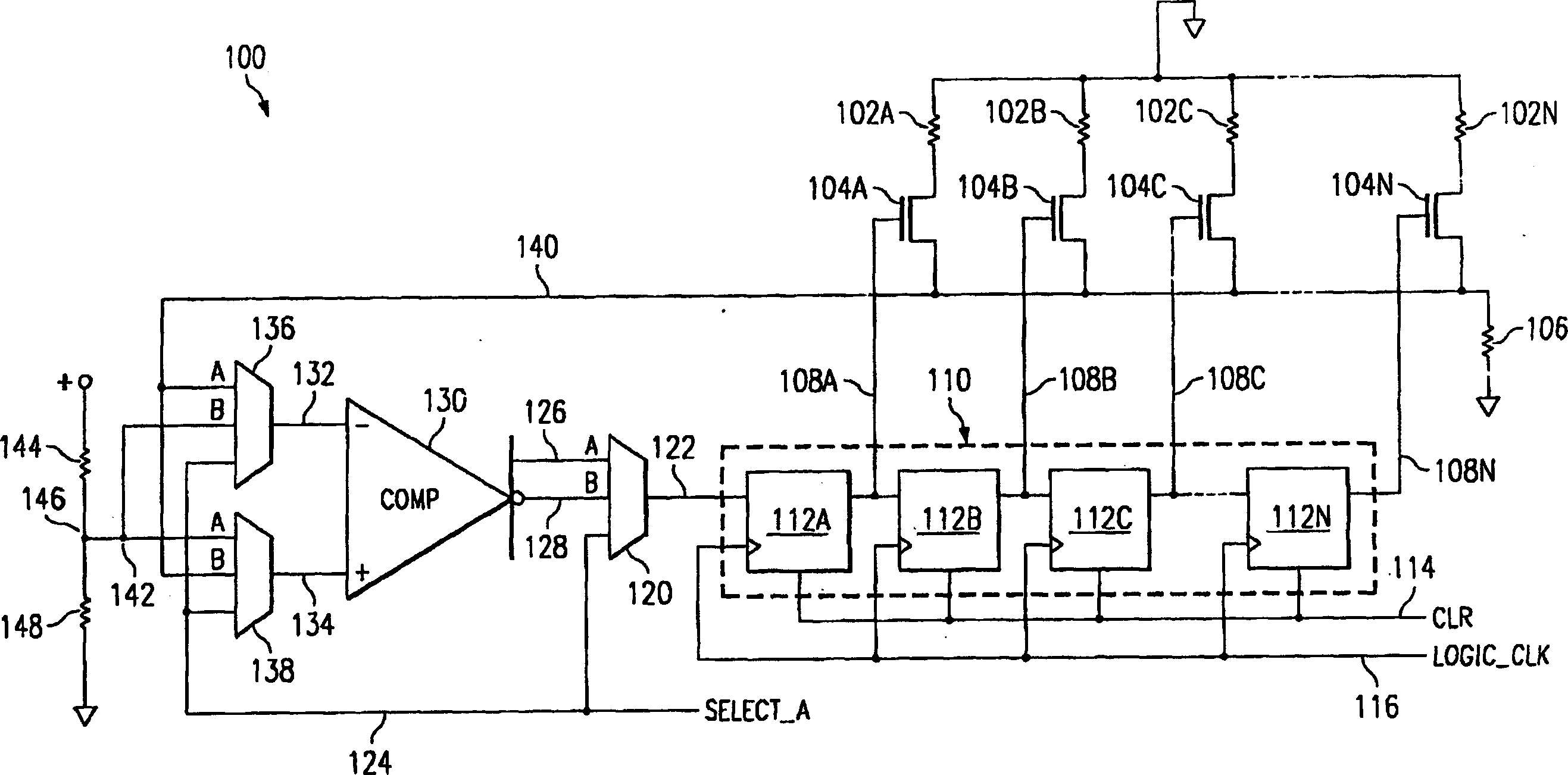
[0018] figure 1 The circuit shown implements the impedance calibration technique of the present invention. Impedance calibration is provided by a plurality of parallel resistors 102A, 102B, 102C...102N, where N is an integer. Each resistor is selected by a corresponding transistor 104A, 104B, 104C...104N. The common end of the resistors is connected to a voltage source and the select end of the resistors is connected to a resistor 106, the other lead of which is connected to ground. Each resistor 104A, 104B, 104C...104N acts as a switch controlled by a signal on line 108A, 108B, 108C...108N respectively. These signals are the outputs of the shift register 110 . Another register arrangement with similar characteristics could also be used. The more transistor 104 is turned on, the less impedance the array becomes.

[0019] Shift register 110 is composed of flip-flops 112A, 112B, 112C . . . 112N, and is connected to flip-flop 112A by serial input 122 . The output of each fl...


PUM


Abstract

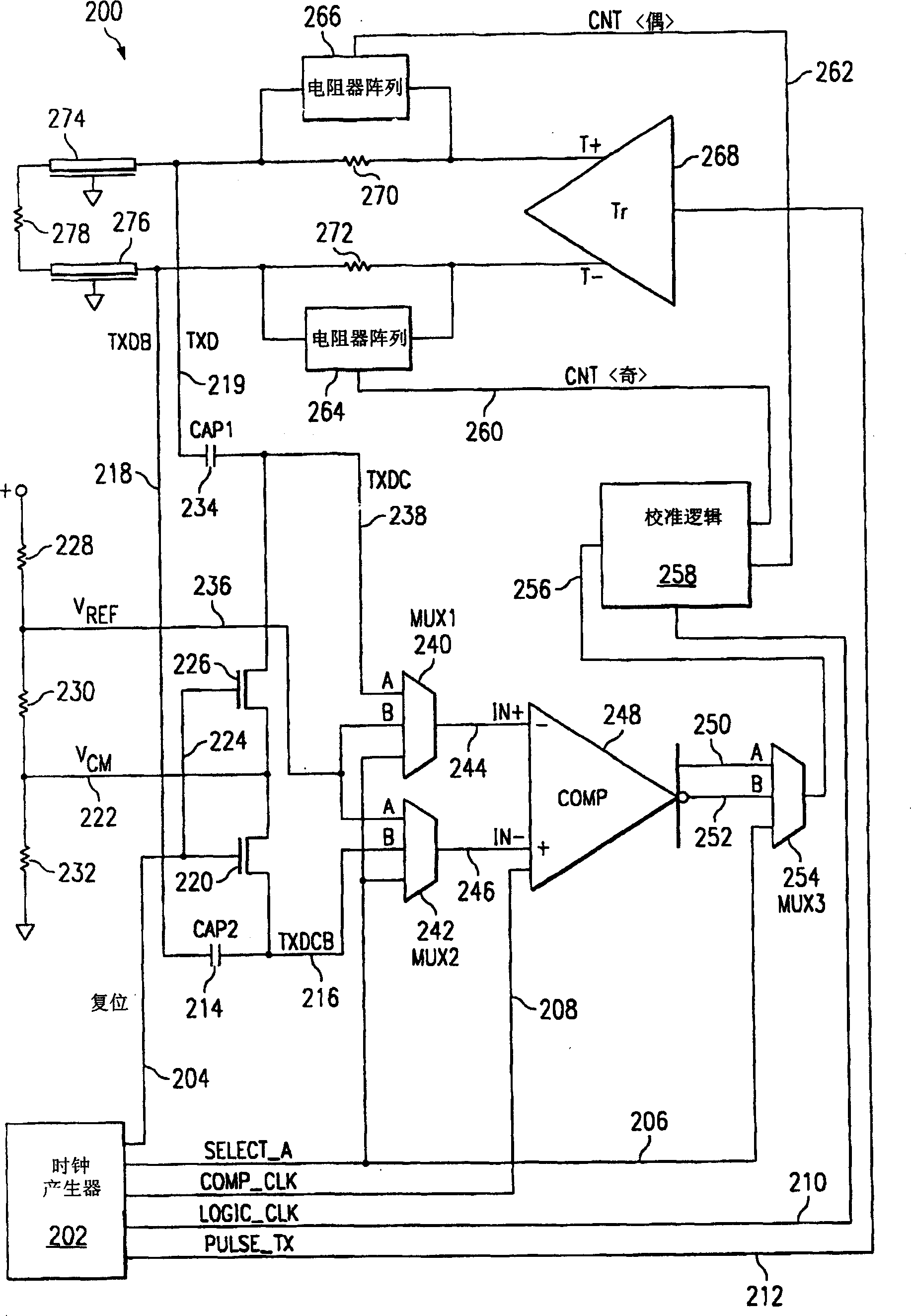
An impedance calibration circuit for a serial ATA (SATA) transmitter has a resistor in series with each leg of the differential output of the transmitter. An array of selectable resistors is in parallel with each of the series resistors. Resistors in the array are selected to be in parallel with the series resistors. A calibration circuit utilizes a comparator to determine when the minimum error in the impedance calibration is reached. Offset errors in the comparator are compensated for by a circuit which determines the center of alternate ones and zeros generated by the comparator when the input signals are within the offset of the comparator, which should be the point of minimum error in the calibration.

Description

field of invention [0001] The present invention relates to impedance calibration circuits, and more particularly to impedance calibration circuits for Serial ATA (SATA) transmitters. Background of the invention [0002] Current computers use Parallel ATA hard drives and other peripherals connected to the controller by 40- or 80-wire ribbon cables. The parallel bus interface reaches its performance limit at a data transfer rate of 133MB / sec. This interface will be replaced by Serial ATA, which will use lower voltage signals in addition to higher data transfer rates. The SATA interface uses 4-conductor cables instead of 80-conductor ribbon cables. The problems associated with ribbon cables, namely blocking airflow within a computer case and folding during assembly are thus eliminated. Data is sent serially as a differential signal pair with a signal amplitude of 250mV, which is much smaller than the 3 or 5 volts used for the parallel ATA interface. [0003] The SATA interf...

Claims


Application Information

Patent Timeline
IPC IPC(8): H03K19/00H04L25/02
CPCH04L25/0278H03K19/0005H04L25/028H04L25/0272
Inventor 池奥孝幸莲沼隆难波健治
Owner TEXAS INSTR INC
Learn More