
Screw compressor

A screw compressor and screw technology, applied in the direction of rotary piston machinery, mechanical equipment, engine components, etc., can solve the problems of liquid refrigerant, insufficient lubrication of cylindrical roller bearings, etc., to eliminate the need to use oil, The effect of simplifying the structure and increasing the cost

Inactive Publication Date: 2004-05-26
KOBE STEEL LTD
View PDF1 Cites 12 Cited by
  • Summary
  • Abstract
  • Description
  • Claims
  • Application Information

AI Technical Summary

Problems solved by technology

However, in the case of using cylindrical roller bearings, it is difficult to make a liquid refrigerant with a lower viscosity than oil exist in the line contact portion between the cylindrical rollers and the inner and outer rings, so insufficient lubrication will cause cylindrical Seizure Problems of Roller Bearings

Method used


Image

  • Screw compressor
  • Screw compressor
  • Screw compressor

Examples


Embodiment Construction

[0024] Embodiments of the present invention will be described below with reference to the accompanying drawings.

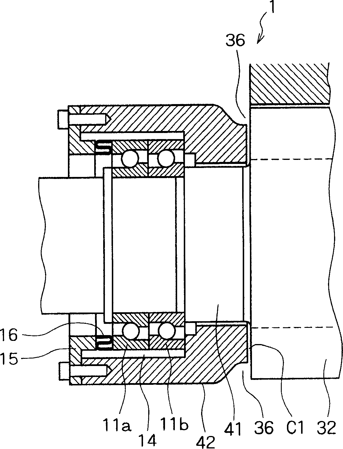
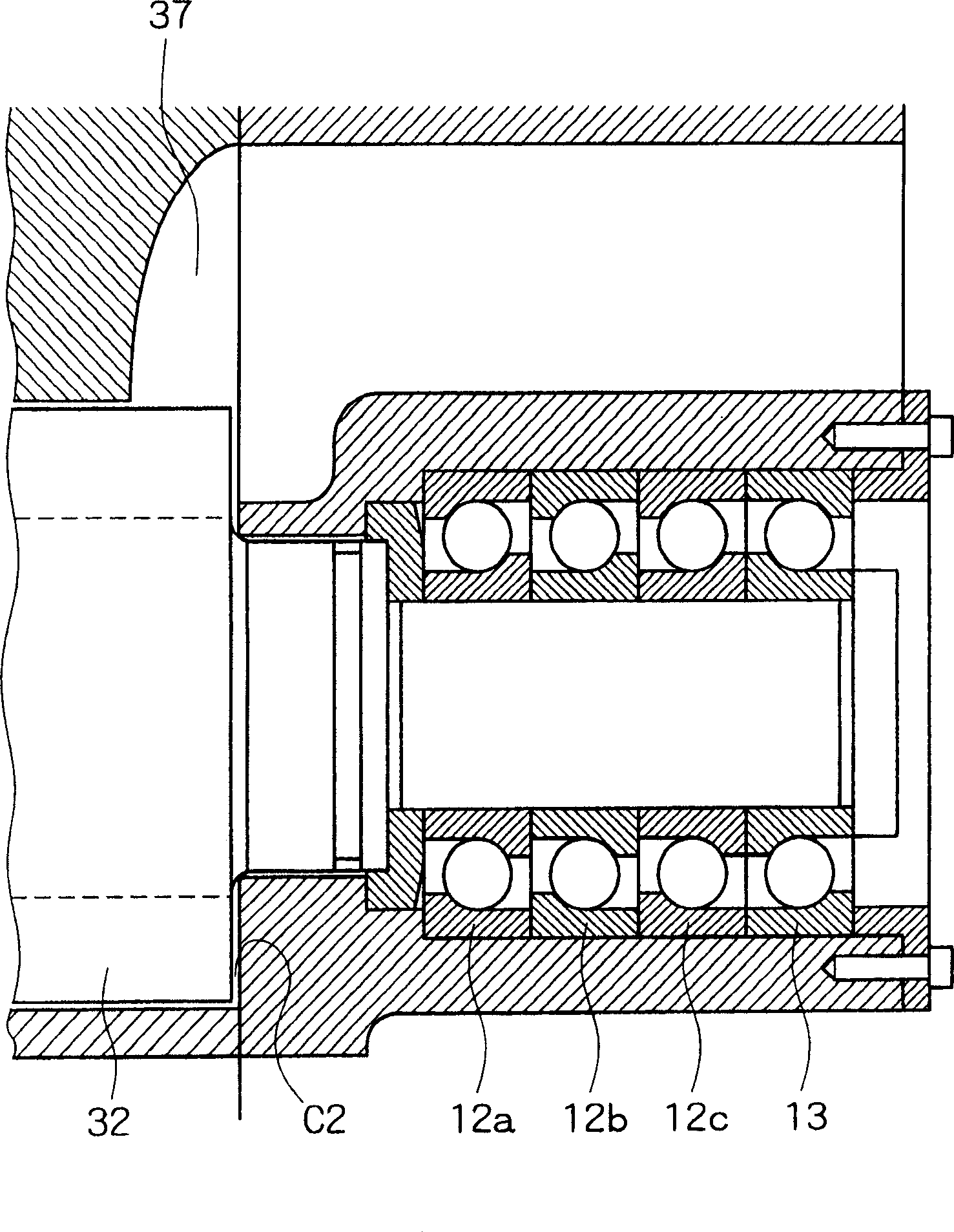
[0025] Figure 1-3 A screw compressor for a refrigeration device according to the invention is shown.

[0026] The screw compressor 1 has a pair of intermeshing male and female rotors 32 and a motor 33 in an integral housing 31 . A gas inlet 35 is formed at one end of the integral case 31 , and the gas inlet 35 is provided with a filter 34 . The discharge port 36 is formed at one end of the screw rotor 32 near the motor 33 , and the discharge port 37 is formed at the opposite end of the screw rotor 32 .

[0027] The suction side rotor shaft 41 of one of the paired male and female rotors 32 is as figure 1 As shown, the rotor shaft 41 is connected to the input shaft 49 of the motor 33 so as to rotate integrally, and the motor 33 rotates the screw rotor 32 .

[0028] When the screw compressor 1 is applied to a refrigeration device, the gaseous refrigerant enters...


PUM


Abstract

In a screw compressor for a refrigerator, suction-side rotor shafts of screw rotors are supported rotatably by angular ball bearings for forward thrust load, an annular gap is formed between the angular ball bearings and a suction-side bearing casing, and outermost end faces of outer rings of the angular ball bearings are pressed through a spring member by means of a presser member fixed to an end face of the suction-side bearing casing, whereby the angular ball bearings are held movably in the thrust direction within the suction-side bearing casing. Discharge-side rotor shafts of the screw rotors are supported rotatably by angular ball bearings for forward thrust load and an angular ball bearing for reverse thrust load which are held at predetermined certain positions within a discharge-side bearing casing. A screw compressor which permits structural simplification, reduction of size, and lightening of a maintenance burden is provided.

Description

technical field [0001] The present invention relates to screw compressors, and more particularly to screw compressors for compressing refrigerants in refrigeration appliances. Background technique [0002] So far, screw compressors for refrigeration applications are known, (eg US Patent No. 6183227). [0003] Screw compressors are generally divided into oil-cooled screw compressors and oil-free screw compressors. In an oil-cooled screw compressor, oil is supplied into the rotor cavity to seal between the rotors; to seal between the rotor and the inner wall of the rotor cavity; to cool the portion whose temperature increases due to compression; and Used for lubrication. In the oil-free screw compressor, oil is not supplied into the rotor chamber, the bearing portion is completely isolated from the rotor chamber by sealing, and the synchronous gear is used to transmit rotational driving force between the female rotor and the male rotor. For the structure of the compressor b...

Claims


Application Information

Patent Timeline
Patent Type & Authority Applications(China)
IPC IPC(8): F01C21/02F04C18/16F04C23/00F04C29/00F04C29/02
CPCF04C23/008F04C2240/50F01C21/02F04C18/16Y10S418/01
Inventor 壶井生
Owner KOBE STEEL LTD
Learn More