
Small omnidirectional two-conical antenna for radio communication

A wireless communication, biconical technology, applied to antennas, antennas, radio/inductive link selection arrangements on movable objects, etc., can solve problems such as communication quality deterioration, impedance mismatch, etc.

Inactive Publication Date: 2004-05-12
SAMSUNG ELECTRONICS CO LTD
View PDF0 Cites 0 Cited by
  • Summary
  • Abstract
  • Description
  • Claims
  • Application Information

AI Technical Summary

Problems solved by technology

However, considering that the wavelength is in the air, the size of the conventional pulse antenna is much larger than that of the antenna for mobile communication terminals.
Moreover, in the conventional pulse antenna, since the TEM wave cannot be incident on the interface according to Brewster's angle, impedance mismatch occurs on the interface, therefore, pulse reflection occurs on the interface, and the communication quality deteriorates rapidly

Method used


Image

  • Small omnidirectional two-conical antenna for radio communication
  • Small omnidirectional two-conical antenna for radio communication
  • Small omnidirectional two-conical antenna for radio communication

Examples


Embodiment Construction

[0030] A small omnidirectional biconical antenna for mobile communication according to a preferred embodiment of the present invention will be described below with reference to the accompanying drawings. In the drawings, the thicknesses of layers or regions are exaggerated for the convenience of describing the present invention clearly.

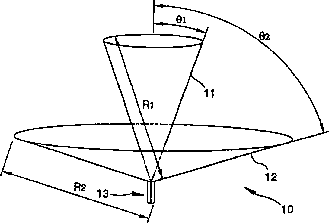
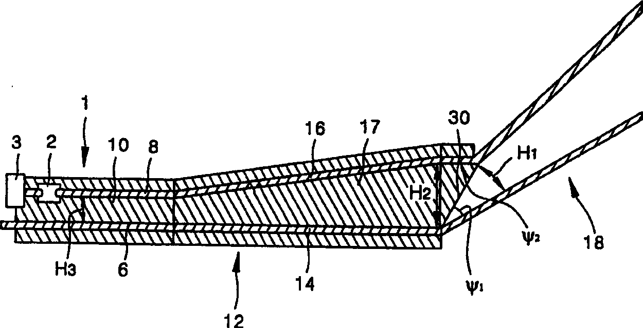
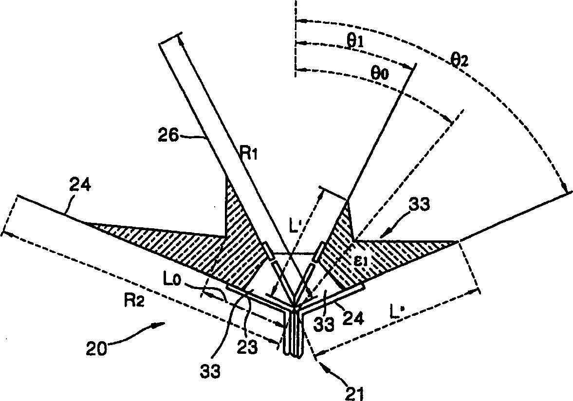
[0031] The antenna of the present invention is a pulse transmitting and receiving antenna, which can be used for communication using electromagnetic pulses of ultra-wide band (UWB), and whose basic shape is a biconical antenna. A dielectric is inserted between the two conical conductors forming the basic structure of the biconical antenna to reduce the physical size of the overall antenna. The medium is injected so that the shortest distance connecting two tapered conductors along the interface between the conductor and the external space, that is, the surface of the conductor is a logarithmic spiral curve. Therefore, the pulse electric fiel...


PUM


Abstract

A biconical antenna for wireless communications includes a conical upper conductive body and a conical lower conductive body having a common apex, which is used as a power feed point, wherein a space between the conical upper and lower conductive bodies is filled with a dielectric material such that a shortest distance connecting the conical upper and lower conductive bodies along a surface of the dielectric material is a curve at which an incident angle of an incident wave incident on the surface of the dielectric material through the dielectric material from the common apex is a Brewster angle over the entire surface of the dielectric material.

Description

technical field [0001] The invention relates to an antenna for wireless communication, in particular to a small omnidirectional biconical antenna suitable for mobile communication. Background technique [0002] Unlike conventional narrow-band wireless communication, wireless communication using pulses (hereinafter referred to as pulse communication) uses an extremely wide frequency band. Pulse communication is known as a communication method capable of high-speed data transmission with extremely low power. Pulse communication has been used in the radar field before. In order to improve the performance of the radar, in addition to the study of the antenna radiation pattern, research is focused on obtaining wide-band operation and high gain. [0003] However, with the rapid development of mobile communication technology, a lot of effective research has been done on the application of the advantages of pulse communication to mobile communication. Although pulse communication...

Claims


Application Information

Patent Timeline
Patent Type & Authority Applications(China)
IPC IPC(8): H01Q13/04H01Q19/08
CPCH01Q13/04H01Q19/08
Inventor 权度熏
Owner SAMSUNG ELECTRONICS CO LTD
Learn More