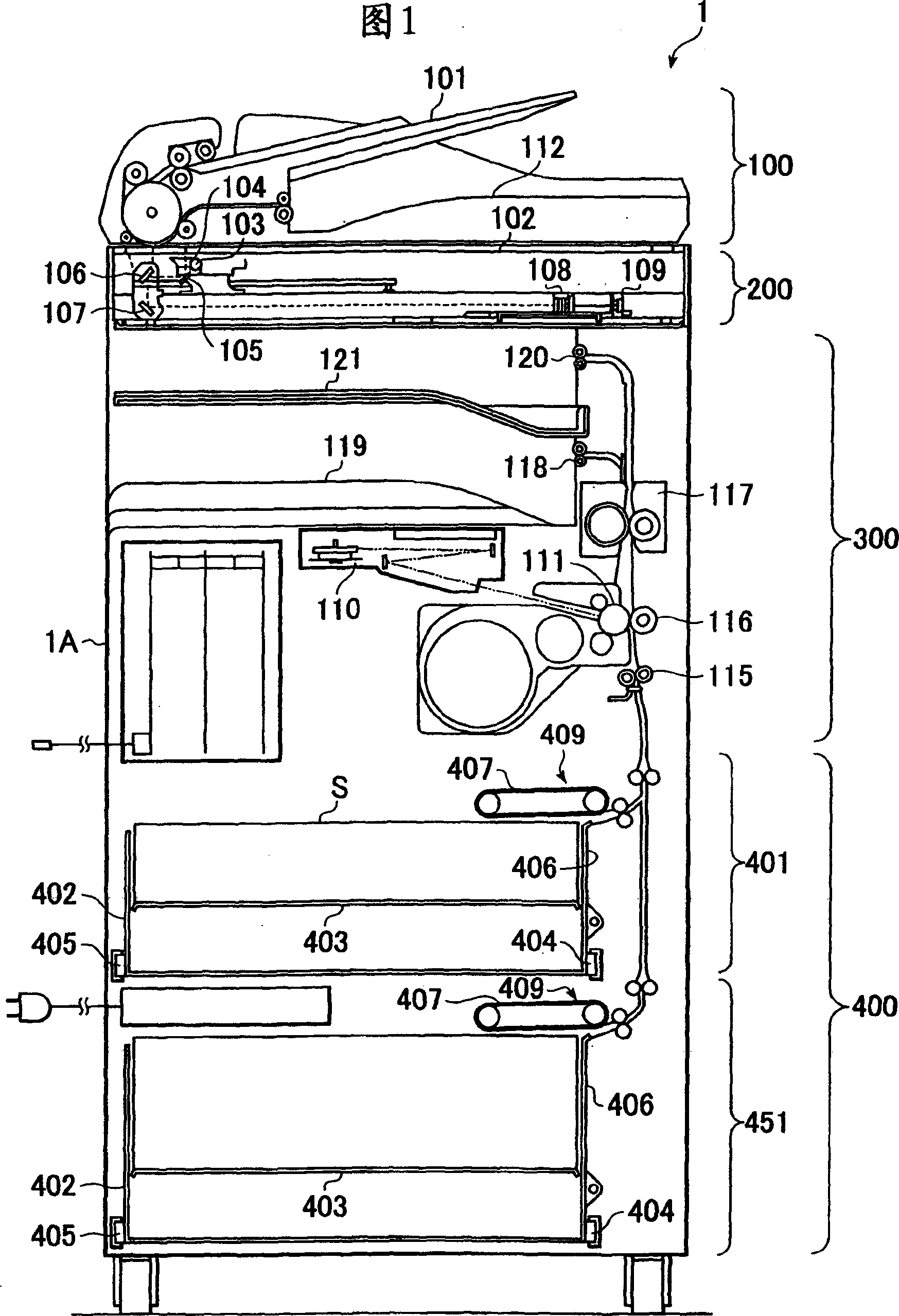
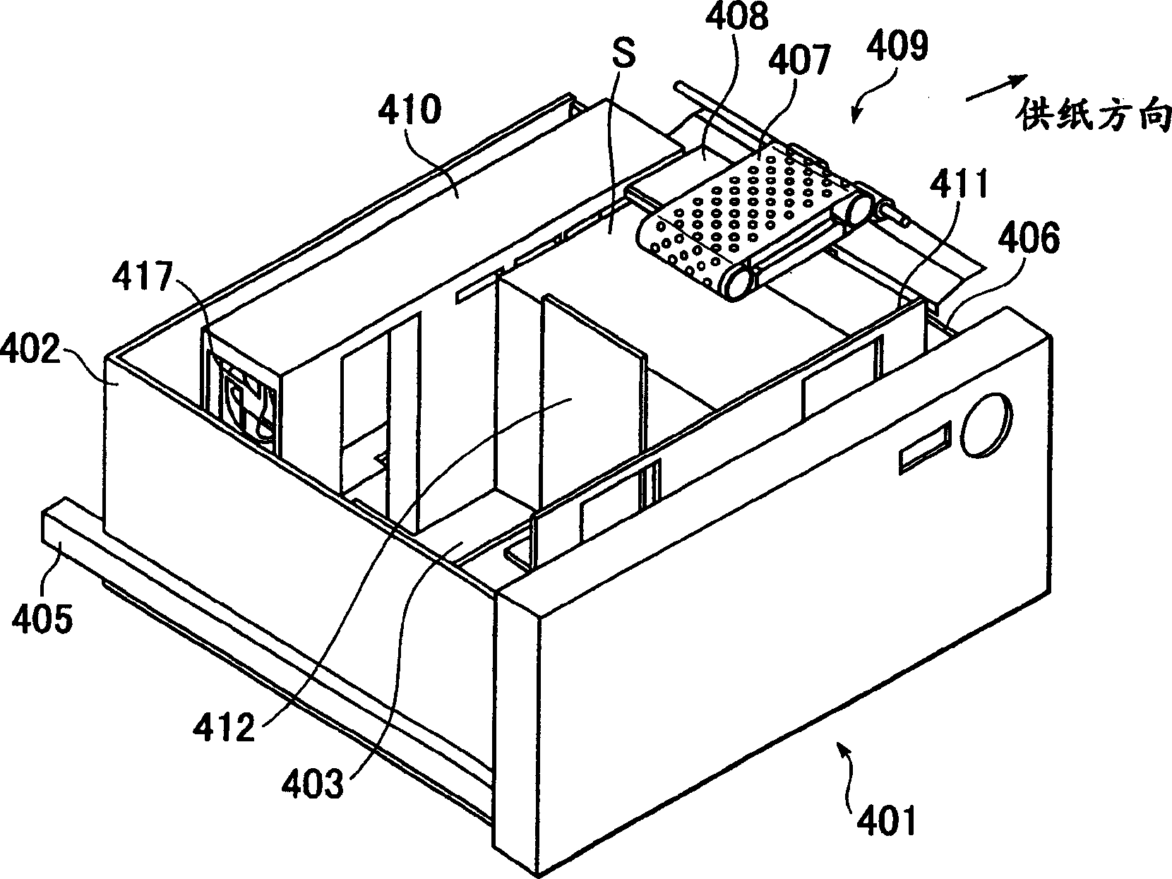
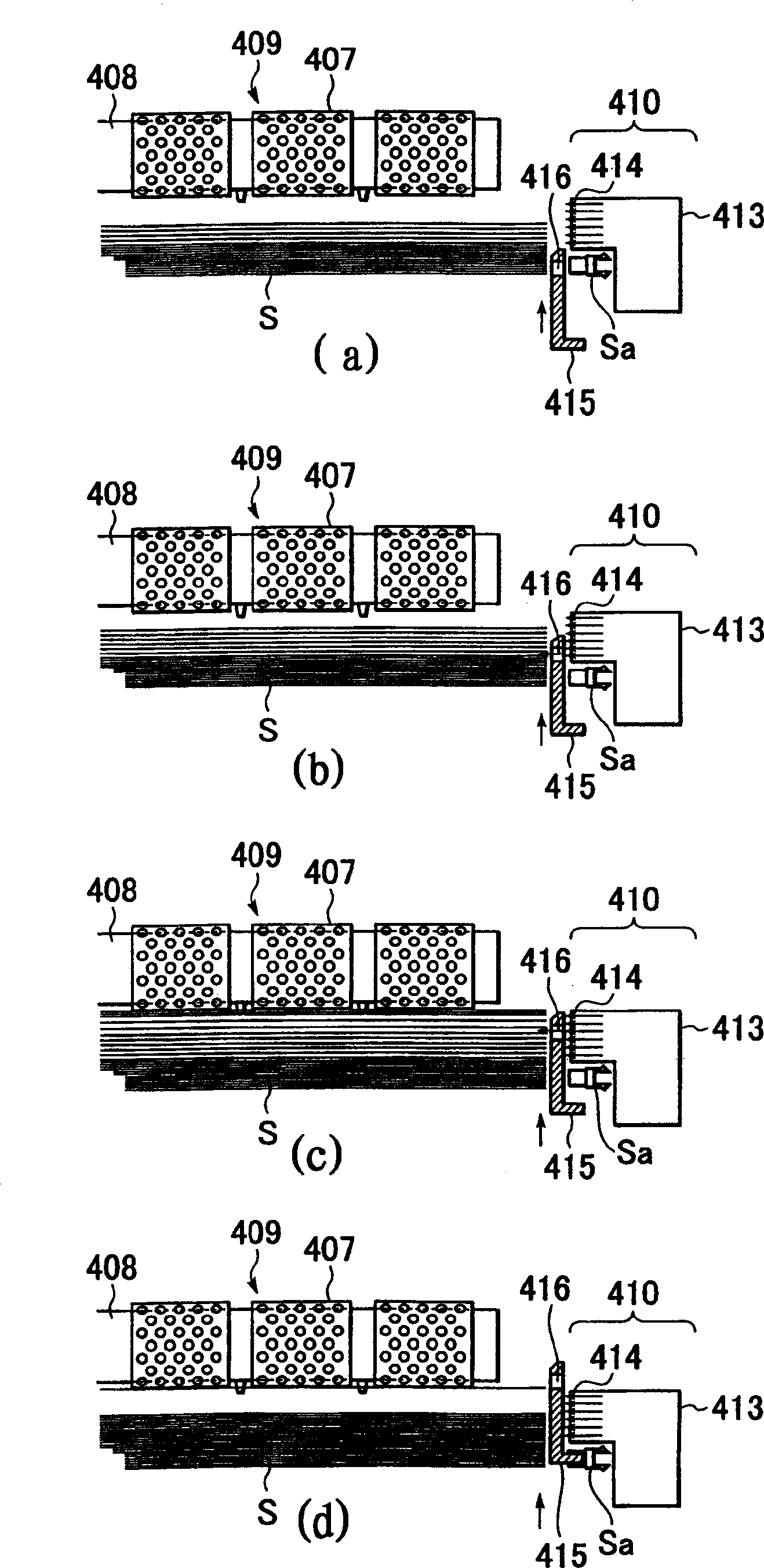
Paper feeder and image forming device
A technology of supplying device and paper, applied in the directions of transportation and packaging, separation of objects, separation of piles, etc., can solve problems such as difficult separation
- Summary
- Abstract
- Description
- Claims
- Application Information
AI Technical Summary
Problems solved by technology
Method used
Image
Examples
Embodiment 2
[0048] Below, refer to Figure 5 Embodiment 2 of the present invention will be described. It should be noted that, regarding the reference numerals in the drawings, the same reference numerals are assigned to the same structures as those of the above-mentioned first embodiment, and the description thereof will be omitted.
[0049] In this embodiment, an ejection pipe 413 is provided on the top end side of the sheet bundle in the sheet conveying direction. In addition, a separation nozzle 419 is provided on a separation pipe 418 connected to a separation fan (not shown), and the separation air is supplied obliquely toward the adsorption belt 407 through the separation nozzle 419 . This separated air is effective in making only the uppermost paper stick to the suction belt and separating and dropping the next paper below.
[0050] In the present embodiment, the shutter 415 starts from the highest position ( Figure 5 (a)) to the lowest position ( Figure 5 (b)) reciprocating...
Embodiment 3
[0054] Below, refer to Figure 6 and Figure 7 Embodiment 3 of the present invention will be described. It should be noted that, regarding the reference numerals in the drawings, the same reference numerals are assigned to the same structures as those of the first and second embodiments described above, and the description thereof will be omitted.
[0055] In this example, if Figure 6 and Figure 7 As shown, when the drive of the adsorption belt 407 (work), the wind speed of the injection air is set near the minimum wind speed (refer to Figure 7 (a)). The wind speed of the sprayed air can be based on the position of the shutter 415, the strength of the sprayed air supply source, or any one of the combined effects of the two. According to this, the paper is fed at a timing when the blowing air velocity is sufficiently low, so that it is possible to provide a paper feeding device in which the above-mentioned multiple sheets are hardly fed together.
[0056] In addition, ...
Embodiment 4
[0059] Below, refer to Figure 8 Embodiment 4 of the present invention will be described. It should be noted that, regarding the reference numerals in the drawings, the same reference numerals are assigned to the same structures as those of the first and second embodiments described above, and the description thereof will be omitted.
[0060]In this embodiment, the swing nozzle 421 of the air direction variable member that can rotate the upper side end of the paper bundle in the vertical direction is provided in the ejection pipe 413 provided on the top end side of the paper bundle. The swing nozzle 421 sprays continuously toward the side end of the sheet bundle S Figure 8 (a) up, Figure 8 (b) to the horizontal direction, Figure 8 (c) Downward air. The oscillating nozzle 421 sprays air while rotating up and down, so it can continuously supply air with changing wind direction to the bundle of paper, so that the air flows into the adsorbed paper or the gap between the loa...
PUM
 Abstract
Description
Claims
Application Information
 - R&D
- Intellectual Property
- Life Sciences
- Materials
- Tech Scout
- Unparalleled Data Quality
- Higher Quality Content
- 60% Fewer Hallucinations
Browse by: Latest US Patents, China's latest patents, Technical Efficacy Thesaurus, Application Domain, Technology Topic, Popular Technical Reports.
© 2025 PatSnap. All rights reserved.Legal|Privacy policy|Modern Slavery Act Transparency Statement|Sitemap|About US| Contact US: help@patsnap.com


