
Compressor

A technology of compressors and two-stage compressors, applied in compressors, irreversible cycle compressors, refrigerators, etc., can solve problems such as performance degradation, large pressure difference, and pressure difference

Inactive Publication Date: 2004-03-17
HITACHI JOHNSON CONTROLS AIR CONDITIONING INC
View PDF1 Cites 28 Cited by
  • Summary
  • Abstract
  • Description
  • Claims
  • Application Information

AI Technical Summary

Problems solved by technology

Degraded performance due to refrigerant leakage due to the pressure difference between the closed container and the compression element
Also, since the minimum sealing length is small and the pressure difference is large, leakage loss at the compression element 20 for low pressure will become a cause of further performance degradation

Method used


Image

  • Compressor
  • Compressor
  • Compressor

Examples


Embodiment Construction

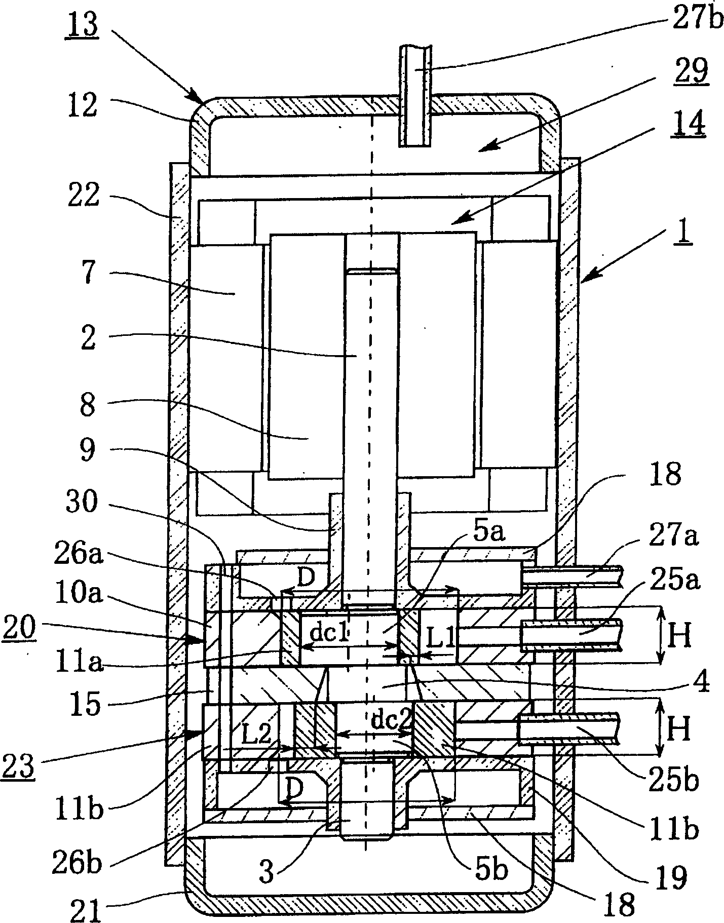
[0042] Hereinafter, embodiments of the present invention will be described with reference to the drawings. Among them, for Figure 14 The symbols used for the same constituent elements in , for easy understanding of the embodiments of the present invention, are figure 1 The same notation is also used in .

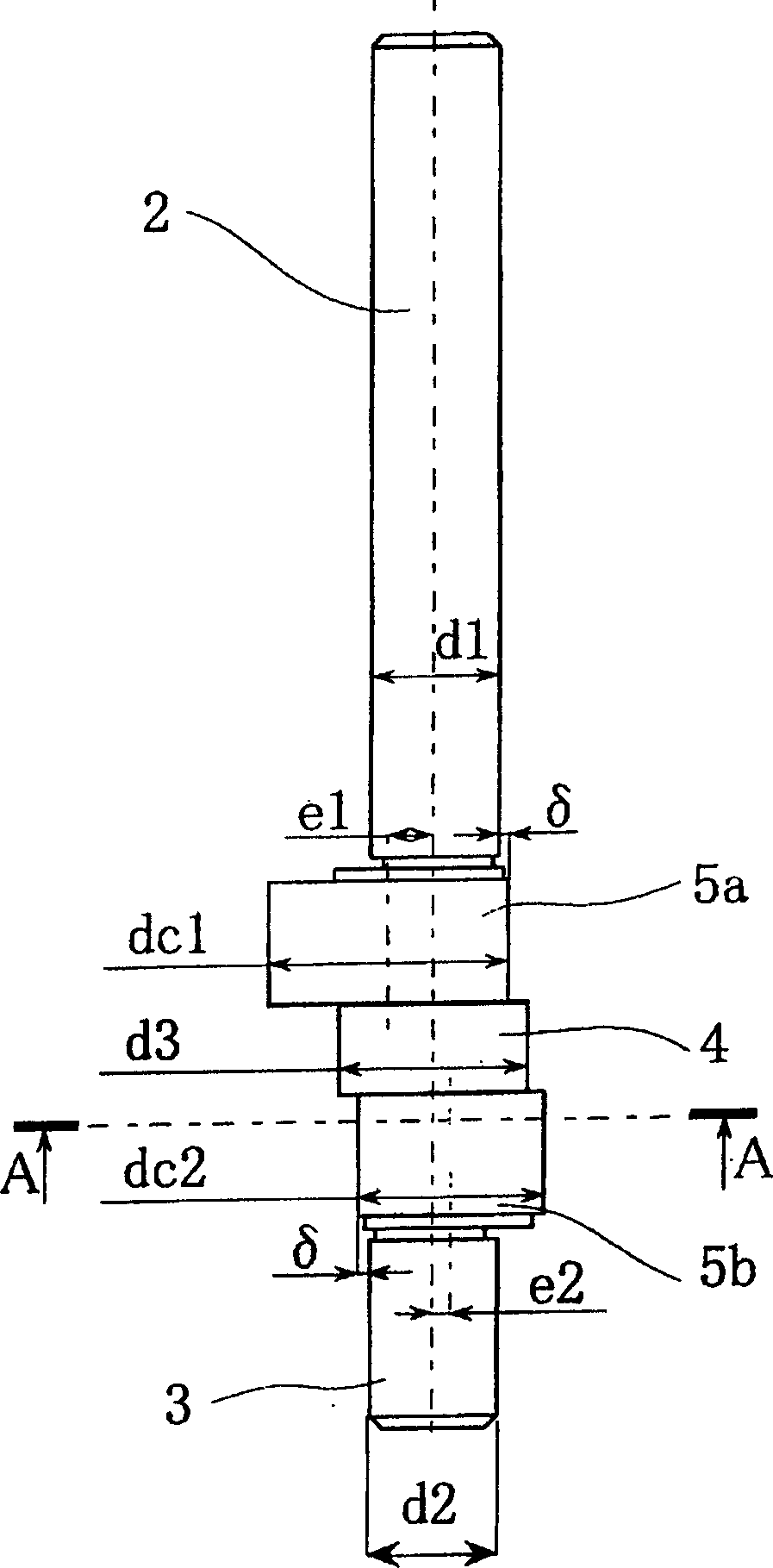
[0043] exist figure 1 Here, the outer diameter dc2 of the eccentric portion 5b of the high pressure compression element 23 is set smaller than the outer diameter dc1 of the eccentric portion 5a of the low pressure compression element 20 . However, the eccentricity e1, e2, cylinder inner diameter D, height H, and roller outer diameter dr, that is, the discharge amount Vcc are the same as the conventional one.

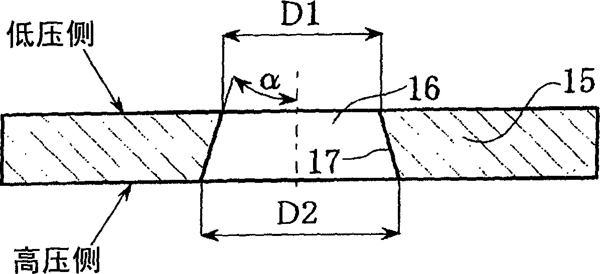
[0044] figure 2denotes the cross-sectional shape of the intermediate partition 15 . The intermediate partition plate 15 has the front end shaft 3 , the eccentric portion 5 b , and a through hole 16 for penetrating the intermediate shaft 4 . The diameter D1 of ...


PUM


Abstract

A rotary two-stage compressor comprises: a motor having a rotary shaft; and a rotary compression element where a compression element for low pressure, a middle partition board, and a compression element for high pressure are laminated in lamination successively from the motor side for integration in a closed container, thus performing the eccentric rotation of the compression element for low pressure and the compression element for high pressure for drive by two eccentricity sections being provided at the rotary shaft. The compressor also has a through hole for passing the rotary shaft to the intermediate partition board and the through hole is set to be nearly in a truncated cone shape. To improve the degree of design freedom in an intermediate shaft by reducing the refrigerant leakage loss and mechanical loss of a two-stage compressor.

Description

technical field [0001] The present invention relates to a rotary two-stage compressor used in an air conditioner, a refrigerator, etc., and more particularly to a high-efficiency rotary two-stage compressor with a high degree of freedom in design around a rotating shaft. Background technique [0002] Figure 14 A structure of an existing rotary two-stage compressor is shown. The compressor 101 has a motor 14 including a stator 7 and a rotor 8 inside a closed container 13 including a bottom cover 21 , a casing 22 , and an upper cover 12 . A crankshaft with a rotating shaft 2 connected to an electric motor 14 is pivotally supported in a main bearing 9 and a secondary bearing 19 . With respect to the rotary shaft 2 , the low-pressure compression element 20 , the intermediate partition plate 15 , and the high-pressure compression element 23 are stacked in layers in order from the motor 14 side to form an integral body. [0003] In this rotary two-stage compressor, two eccentri...

Claims


Application Information

Patent Timeline
IPC IPC(8): F04C23/00F04C18/32F04C18/356F04C29/00F25B1/04F25B1/10
Inventor 久保田淳关上和夫中村启夫
Owner HITACHI JOHNSON CONTROLS AIR CONDITIONING INC
Learn More