
Hinge

A hinge and hinge arm technology, applied in the hinge field, can solve the problem of high manufacturing cost

Inactive Publication Date: 2004-03-10
ARTURO SALICE
View PDF1 Cites 6 Cited by
  • Summary
  • Abstract
  • Description
  • Claims
  • Application Information

AI Technical Summary

Problems solved by technology

Such hinges are known to be expensive to manufacture due to the need for a pinion-toothed segment structure to transmit the damping force

Method used


Image

  • Hinge
  • Hinge
  • Hinge

Examples


Embodiment Construction

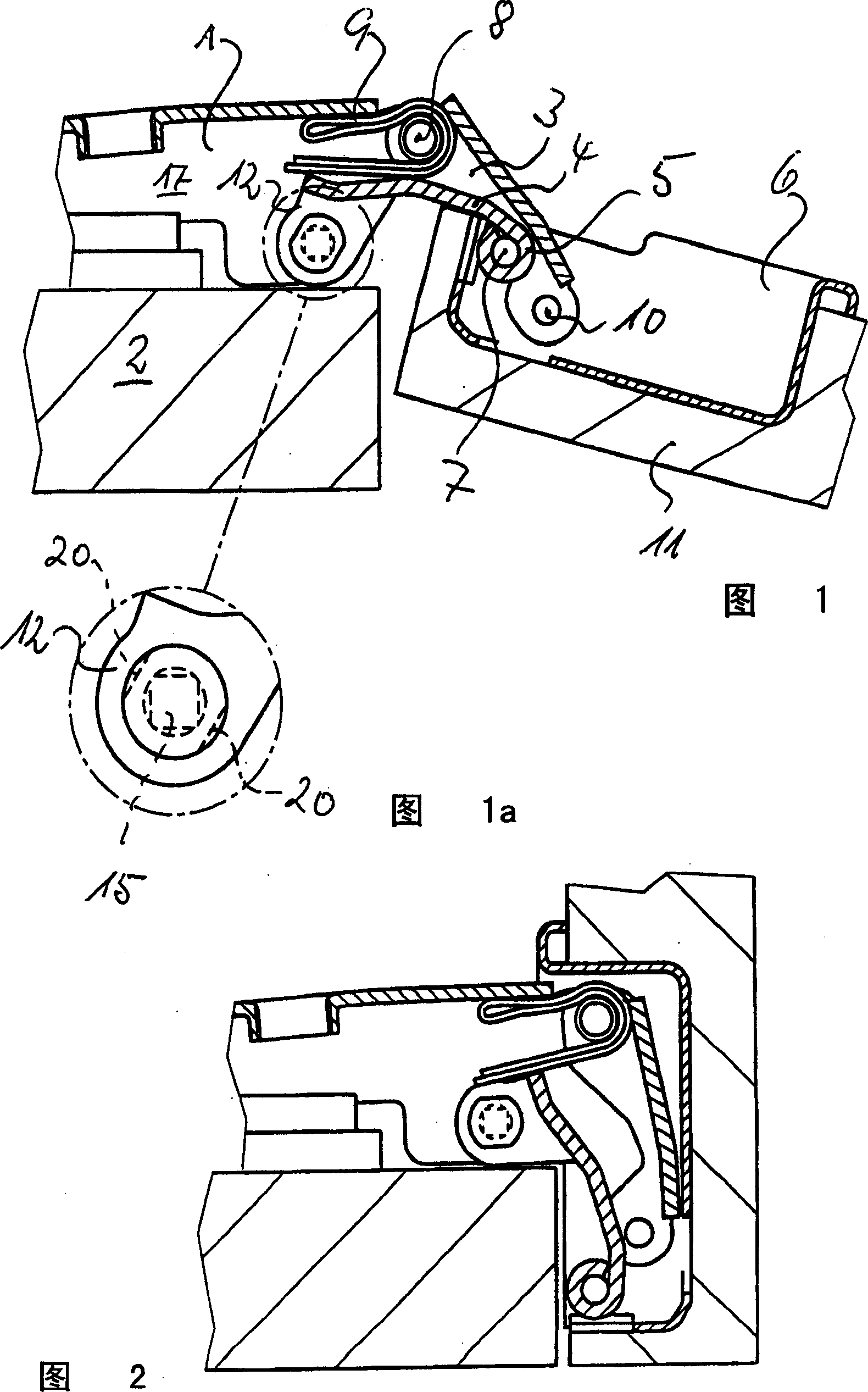
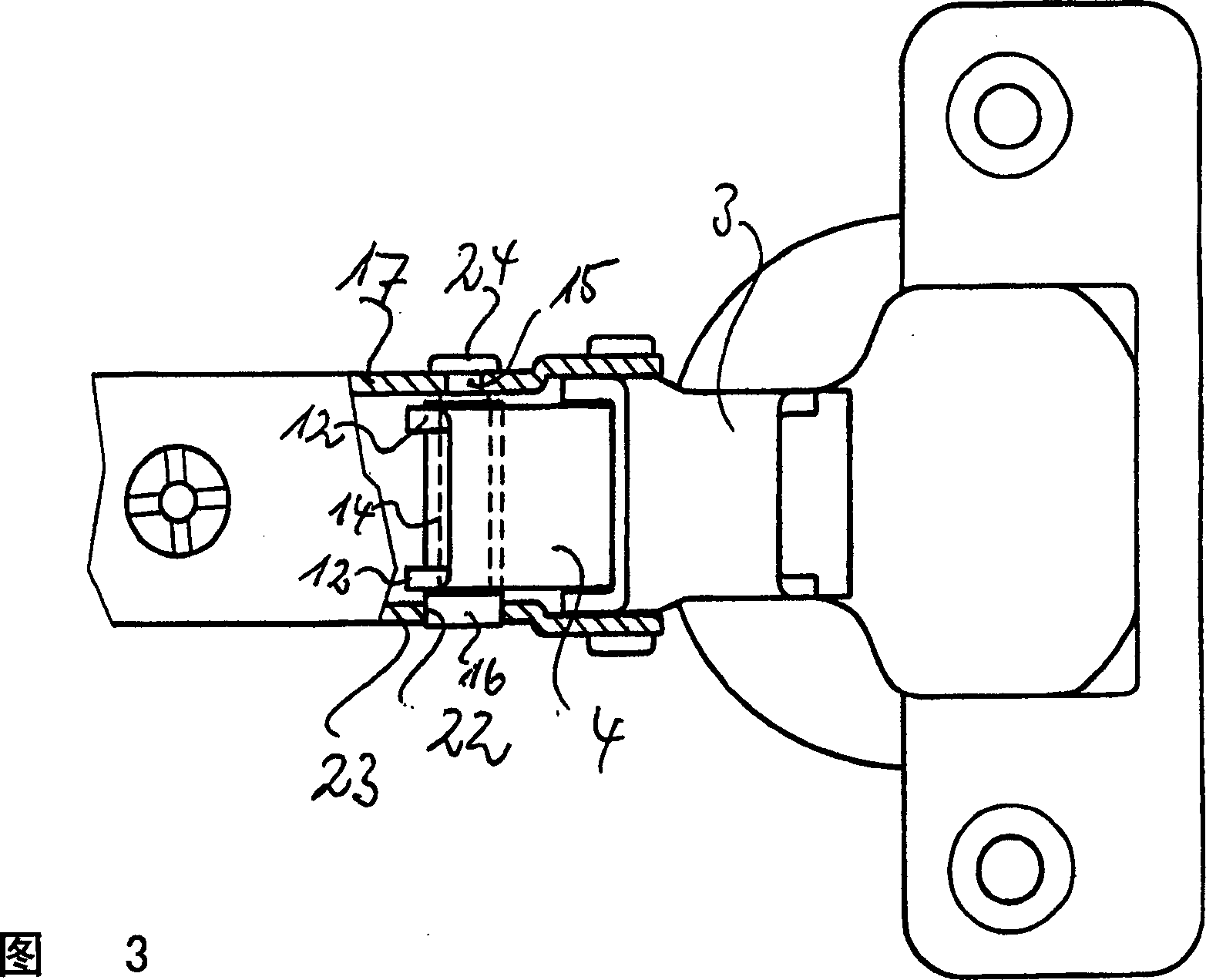
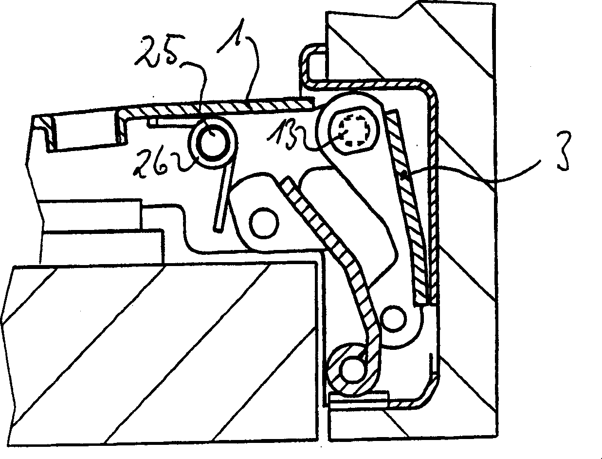
[0022] Figure 1 to Figure 5 The double guide hinges shown in include conventional double guide hinges, but with the feature that they can be fitted with a rotational damper in the form of a shaft damper to dampen the closing movement of the door or hinge plate .

[0023] The double guide hinge shown in the figures comprises a U-shaped hinge arm 1 made of zinc-based die-cast alloy or stamped metal parts, which is usually fixed to a cupboard wall or body 2 . The ends of the guides 3, 4 are supported between the legs of the hinge arm 1, wherein both ends of the guide 3 and the rear end of the guide 4 are provided with U-shaped inclined support lugs, which are provided with hole. The outer end of the guide 4 is provided with a roll eye 5 supported on a bolt 7 housed in a hinge cup 6 . A supporting bolt 8 is accommodated between the legs of the hinge arm 1, the inner end of the outer guide 3 is supported on the supporting bolt 8, and a double hairpin curved leaf spring 9 is ins...


PUM


Abstract

The movement of a hinge, preferably for furniture, comprising a hinge arm or a fixed-body hinge section and a pivotable hinge section flexibly connected thereto, is damped by a rotation damper at least damped over part of the closure path to the closed position. In order that the hinge can be manufactured at reduced cost, the rotation damper is an axial damper whose axis forms a hinge axis of the hinge and whose cylinder is fixedly connected to the hinge section which is pivotably supported on the axis.

Description

technical field [0001] The invention relates to a hinge particularly suitable for furniture, said hinge comprising a hinge arm or a hinge part fixed to a main body and a pivotable hinge part flexibly connected thereto, the pivotable hinge part being Movement toward the closed position is damped at least part of the closing path. Background technique [0002] Such a hinge is known, for example from DE 201 04 100 U1. In these known hinges, conventional rotary dampers are used, in which the rotary body, damped by a damping fluid, is located in a cylindrical housing and engages with a toothed segment of one of the pivotable hinge parts. The pinion is positioned on at least one pin of the rotating body supported in the housing cover. Such hinges are known to be relatively expensive to manufacture, since the pinion-toothed segment structure is required to transmit the damping force. Contents of the invention [0003] It is therefore the object of the invention to provide a hi...

Claims


Application Information

Patent Timeline
Patent Type & Authority Applications(China)
IPC IPC(8): E05D3/06E05D11/08E05D11/10E05F1/12E05F5/02E05F5/10F16B2/10F16C11/04
CPCE05F1/1284E05Y2201/21E05Y2600/46E05Y2600/45E05D11/1021E05F5/006E05Y2201/266E05Y2201/254Y10T16/53828E05Y2900/20Y10T16/54038Y10T16/547Y10T16/53833E05D3/142E05D3/06
Inventor 发明人不要求公开其姓名
Owner ARTURO SALICE
Learn More