
Soluting method for protection of loop fault of optical transmission network by four fiber complex section sharing

A shared protection ring and optical transmission network technology, applied in the field of optical transmission, can solve problems such as service interruption of network elements on the ring network, misunderstanding of staff, and high switching level

Inactive Publication Date: 2004-02-04
ZTE CORP
View PDF0 Cites 4 Cited by
  • Summary
  • Abstract
  • Description
  • Claims
  • Application Information

AI Technical Summary

Problems solved by technology

[0012] Question 1: Since network elements A and B have always maintained FS_R-level ring bridge switching, if the working optical fiber of any span on the transmission ring network fails at this time, since the ring switching level of FS_R level is higher than that of the signal failure_span (SF_S) span The segment switching level is high, and the two NEs with faulty working fibers will not be able to start SF_S inter-segment switching to restore services
As a result, services between NEs on the ring network will be interrupted, and the consequences will be extremely serious.
[0013] Question 2. The network management layer is the control layer for the staff on the transmission ring network
At this time, the network management layer has revoked the FS_R network management command of network element A in the A-B direction, but the device layer still maintains the FS_R ring switching. The state of the network management layer and the device layer are inconsistent, which may easily cause misunderstandings and other misoperations by the staff.
[0014] Phenomenon 2: For manual switching_ring (MS_R) network management commands and practice switching_ring (EXE_R) network management commands, due to their low protection level, problem 1 will not occur, but the phenomenon described in problem 2 still exists

Method used


Image

  • Soluting method for protection of loop fault of optical transmission network by four fiber complex section sharing
  • Soluting method for protection of loop fault of optical transmission network by four fiber complex section sharing
  • Soluting method for protection of loop fault of optical transmission network by four fiber complex section sharing

Examples


Embodiment Construction

[0024] The technical solutions of the present invention will be further described below in conjunction with the accompanying drawings and specific embodiments.

[0025] figure 1 It has been explained in the background technology section.

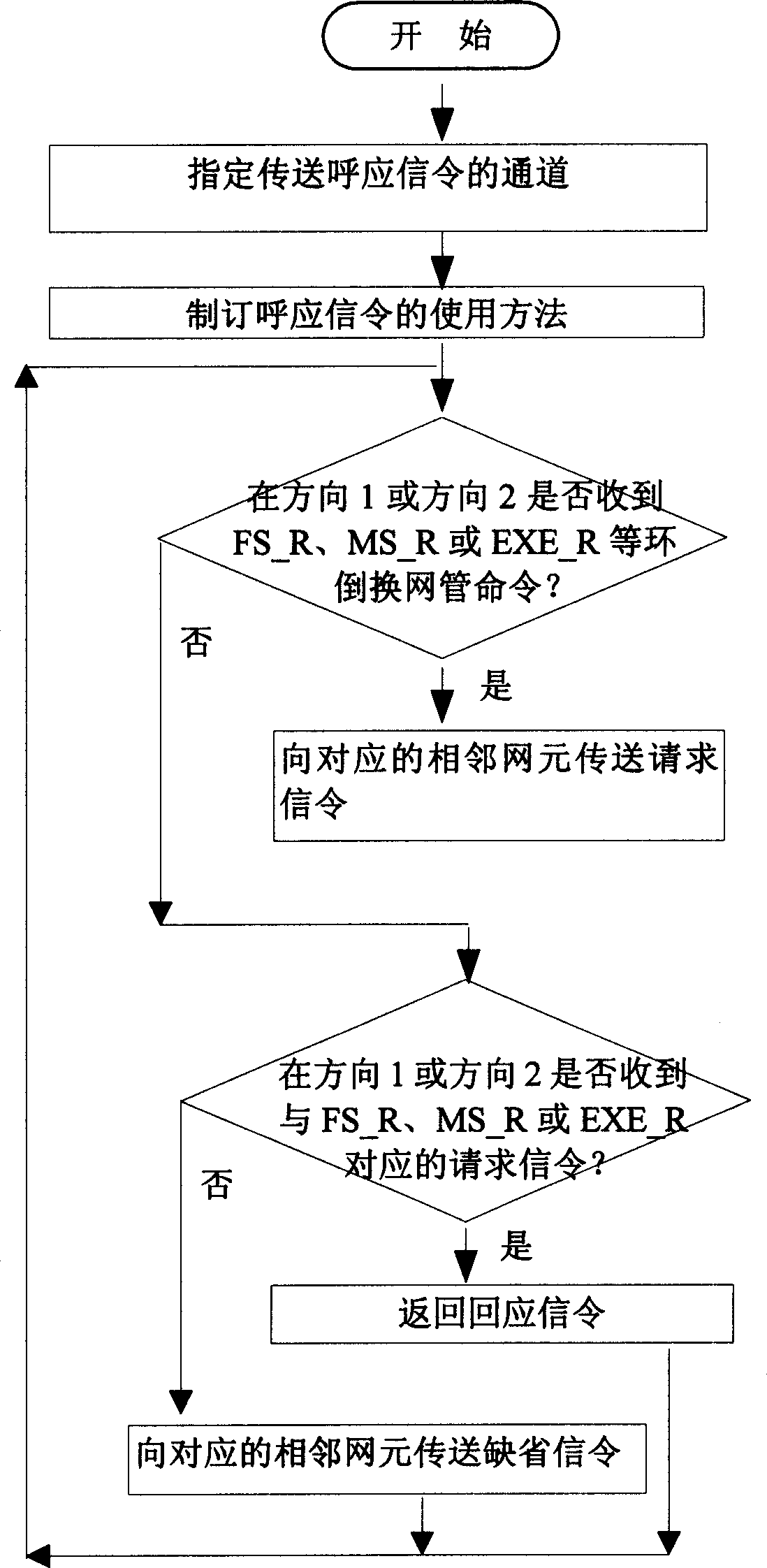
[0026] figure 2 It is a flow chart of the method of the present invention, and the specific process of using the method of the present invention to solve problem 1 and problem 2 is illustrated in conjunction with this figure:

[0027] Assuming that the protection switching protocol signaling is transmitted on the protection fiber, select a channel of the working fiber to transmit the response signaling, for example figure 1 The W1 and W2 working fibers in the Assuming that the protection optical fiber P1 between network elements A and B is interrupted, if network element A has the FS_R network management command in the direction of A->B, the steps to establish ring bridge switching at this time are as follows:

[0028] Step 1: When netw...


PUM


Abstract

A solving method of 4 fibre Multiplex Section Shared Protection Rings fault in optical transmission network. It concerns with following field; 1. appoints certain transmission channel and transmit echo signaling. 2. The net element which is received order that commands PS-R ring inverting the instruction of administration of networks sends the corresponding net elemtn request signaling; after the corresponding net element receives the requests, returns the responses signaling; The net element that neither receives order from administration of networks nor receives request signaling send close-in net element a default signaling. 3. judge transmit net element whether receives PS_R ring inverting the instruction of administration of networks at direction 1 or 2; if it is received then send close-in net element request signaling that corresponds to FS-R; if not enter 4.

Description

technical field [0001] The invention relates to the field of optical transmission, in particular to a fault-solving technology for shared protection rings of four-fiber multiplexing sections of an optical transmission network. Background technique [0002] Multiplex section protection switching is an important method to quickly restore services after a fault occurs in a high-speed optical transmission ring network. The most important module signal in the SDH signal system is the synchronous transfer mode (STM-1), and its rate is 155.52Mbit / s. The higher-level transmission rate of the transmission network is the result of multiplexing the STM-1 signal. The first 81 bytes of the STM-1 signal are defined as section overhead bytes (among them, the first 27 bytes are called regeneration section overhead bytes, and the last 45 bytes are called multiplex section overhead bytes), among which the multiplex Section overhead bytes K1 and K2 are used to transmit multiplex section prot...

Claims


Application Information

Patent Timeline
Patent Type & Authority Applications(China)
IPC IPC(8): H04B10/032
Inventor 孙德胜杨军缪富进
Owner ZTE CORP
Learn More