
Mechanical optical switches

An optical switch and mechanical technology, applied in the field of mechanical optical switches, can solve the problems of switching stability or repeatability, large size, complex structure, etc.

Inactive Publication Date: 2004-02-04
IND TECH RES INST
View PDF11 Cites 3 Cited by
  • Summary
  • Abstract
  • Description
  • Claims
  • Application Information

AI Technical Summary

Problems solved by technology

[0004] The optical switch disclosed in No. 4,239,331, No. 4,303,303, No. 4,322,126, No. 4,790,621, No. 5,000,534, and No. 5,642,446 of the above-mentioned U.S. patent case is to switch the position of the reflector connected to it by the switching device , and the switching devices in these six patents all use offset or rotation to change the position of the mirror, and these six patents have the following characteristics: US No. 4239331, No. 4303303, No. 4322126 All of these patents have the function of a mechanical latch, and the switching devices connected to the mirrors use electromagnetic methods to change the position of the mirrors and then switch the optical path. However, this mechanism will have mechanical wear and tear under long-term use. In addition, prisms are generally used to change the direction of light propagation. Since the angle of light incident on the prism is very sensitive, it is easy to cause an increase in insertion loss. Moreover, the number of single-core fiber collimators used also has a large volume. The risk of being too large; as for the U.S. Patent No. 4790621, it uses too many components and has a complicated structure. Even the stability of the switching device switching the mirror to two positions is questionable, but it has the advantage of a latching function; U.S. Patent No. 5000534 achieves the position of the switching mirror by rotating to switch the optical path, but its volume is too large and does not have the function of locking; U.S. Patent No. 5642446 uses too many components, And the structure is complicated, and has the disadvantage of being too large
[0005] U.S. Patent No. 4948223 and No. 6044186 patent case both use an actuator to move the optical fiber, but the methods used to drive the actuator in the two patent cases are different: the No. 4948223 patent case uses electromagnet switching to move the optical fiber, And No. 6044186 uses bimorph material (bimorph) to move the optical fiber. The common disadvantage of both is to maintain the optical fiber in its position by utilizing the elastic force of the contact between the optical fiber and the bottom surface, so the stability of switching or duplication
[0006] In U.S. Patent No. 5,661,827, the switching device is controlled by an electromagnet to shift the position of the reflector to switch the optical path, but it has the disadvantage of too many components, which makes the cooperation between the components difficult. So it is not easy to mass produce
[0007] As for U.S. Patent No. 5742712, a relay is used to move the position of the reflector to switch the optical path, but it does not have the function of locking
[0008] However, in the No. 6215919 patent case of the United States, the angle of the wedge-shaped optical component used to switch the optical path must meet certain requirements before the optical path can be switched, so it has the disadvantage of being difficult to manufacture.

Method used


Image

  • Mechanical optical switches
  • Mechanical optical switches
  • Mechanical optical switches

Examples


Embodiment Construction

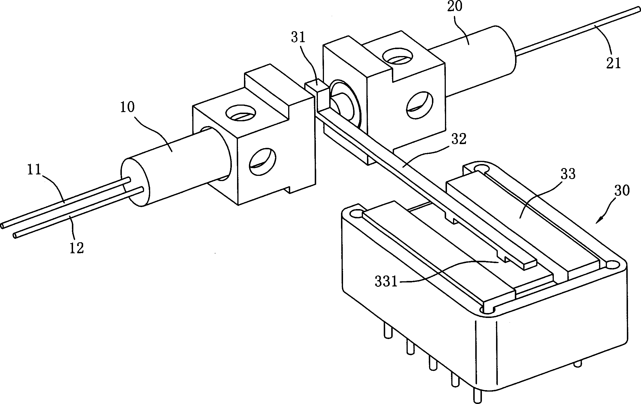
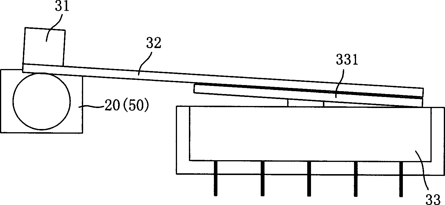
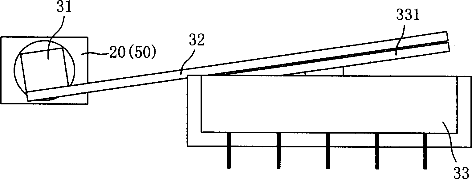
[0032] Such as figure 1 and Figure 2A , 2B As shown, the first embodiment of the mechanical optical switch disclosed in the present invention can selectively reflect light beams and allow light beams to pass through. This mechanical optical switch is a 1×2 optical switch and includes a dual-core optical fiber collimator device (dual-core collimator) 10, single-core fiber collimator (single-core collimator) 20 and switching device 30.

[0033] The dual-core fiber collimator 10 includes a transmitting fiber 11 and a first receiving fiber 12 .

[0034] The single-core fiber collimator 20 has a second receiving fiber 21 , which is located opposite to the dual-core fiber collimator 10 .

[0035] The switching device 30 includes a reflector 31, a cantilever 32 and a relay 33, wherein the reflector 31 is arranged at one end of the cantilever 32, and is movably positioned between the double-core fiber collimator 10 and the single-core fiber collimator 20, and has two The locked p...


PUM


Abstract

The switch includes double optical fibre core collimator, single optical fibre core collimator and switching unit, of which two collimator can be used to emitt and receive lightbeam and they are set in opposite position. The switching unit with reflector set movably in between the two collimators can selectively reflect light beam issued from double optical core collimator to itself for receiving or to let it forward on continuously for being received by single optical fibre core collimator so this is the way that the switching of light path is achieved.

Description

technical field [0001] The invention relates to a mechanical optical switch, which is used to control the traveling direction of light beams. In particular, the 2×1 optical switch architecture can be selectively expanded to a 2×2 optical switch without changing the original switching device. Background technique [0002] Generally speaking, the optical switch (optical switch) is used to control the direction of travel of the beam, and is used to switch the beam of light to a certain place or not, as a switching of the switch, so the optical switch can selectively make a traveling The beam is reflected from the direction it is traveling to another direction, and continues to travel in this other direction, or makes it continue to travel along its direction of travel, and the main way for the optical switch to control the beam is to use the mirror to divert the beam reflection. [0003] At present, there are many patents on optical switches, such as U.S. Patent No. 4239331, N...

Claims


Application Information

Patent Timeline
IPC IPC(8): G02B6/32G02B6/35
Inventor 王应庆胡杰
Owner IND TECH RES INST
Learn More