
Light path folding apparatus

A folding device and optical path technology, applied in optics, optical components, instruments, etc., can solve problems such as must be grasped, small depth of field, short optical path, etc., and achieve the effect of preventing incomplete folding or pulling apart

Inactive Publication Date: 2003-12-31
UMAX DATA SYST
View PDF0 Cites 2 Cited by
  • Summary
  • Abstract
  • Description
  • Claims
  • Application Information

AI Technical Summary

Problems solved by technology

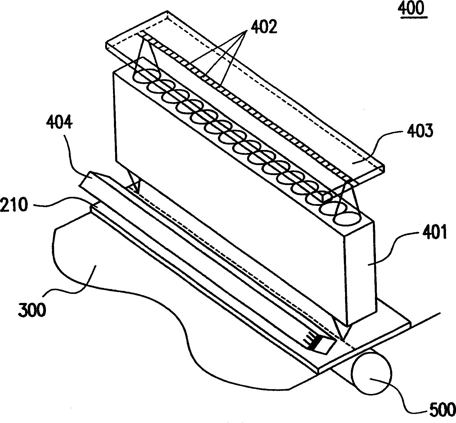
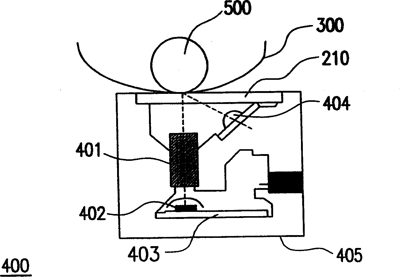
Compared with the general lens imaging method of the charge-coupled device, the self-focus lens imaging advantage of the contact image sensor is that the optical path is short, and the application system can be made light and thin. However, the disadvantage is that the depth of field is small, and the mechanism of the system Both design and control need to be more precise than systems using charge-coupled devices
[0008] To sum up, scanners using contact image sensors have the advantages of small size and easy portability, but their disadvantage is that the depth of field is relatively small, which can easily cause partial image blurring when scanning uneven documents or photos
However, flatbed scanners using charge-coupled devices and general lenses have a better depth of field, but the relative mechanism design of the system cannot be miniaturized, and it is inconvenient to carry, and documents must be placed on a light-transmitting plate. Books or large newspapers or magazines that need to be folded are also inconvenient to operate
Some small-sized flatbed scanners (such as A5 and A6) can be placed on books or large newspapers or magazines that need to be folded to scan downwards, but the scanner must grasp the entire scanning area when picking up and holding it. instrument, it is inconvenient to operate
Even the early hand-held scanners were manually pushed to perform scanning operations, and the scanning quality was easily affected by operational factors

Method used


Image

  • Light path folding apparatus
  • Light path folding apparatus
  • Light path folding apparatus

Examples


Embodiment Construction

[0059] Figure 3a It is a schematic side sectional view of an optical path folding device according to an embodiment of the present invention. The optical scanner of the present invention has a main body casing 1000 and a foldable and collapsible device 1400 that can be used as a handle for easy handling. That is, the optical scanner of the present invention is in the form of a hand-held operation. When a user wants to use the optical scanner for scanning operations, he only needs to hold the foldable device 1400 to make the light-transmitting plate of the main body casing 1000 1200 presses downward against the document 1300 to be scanned, and then selects the required corresponding function buttons 1800 (such as scanning, OCR, photocopying, etc.) on the foldable device 1400 to scan the document 1300 Operation.

[0060] Wherein, the foldable and collapsible device 1400 is pivotally connected to the main body casing 1000 by a rotating shaft 1500, and it can be in a first posi...


PUM


Abstract

The optical path folding device is used in optical scanning instrument with CCD or non-contact image sensor, and setting partial optical path space inside one folding device makes it possible to use common lens with better field depth to reduce the volume of scanning instrument for easy carrying about, holding and operating and to omit driving the scanning instrument while scanning. Reducing the volume of scanning instrument via folding can also save package cost and storing space.

Description

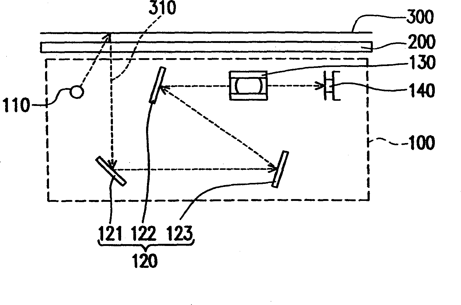
technical field [0001] The present invention relates to an optical path collapsing and folding device, and in particular to an optical path collapsing and folding device applied to an optical system of an optical scanner. Background technique [0002] With the advancement of computer multimedia technology, the progress of image processing is advancing rapidly, driving the advancement of many computer peripheral image processors. Scanners are an example. In just a few years, from palm-sized black and white scanners to full-color high-resolution High-resolution scanners, the images produced are more refined and more realistic, making scanners one of the basic equipment for many computer users. It can scan text or image data of documents, magazines, books, pictures, etc. into the computer and deal with it. [0003] Such as figure 1 As shown, the optical system 100 of the optical scanner includes optical elements such as a light source 110 , an imaging element group 130 , a mi...

Claims


Application Information

Patent Timeline
IPC IPC(8): G02B26/10
Inventor 邱垂桂黄英俊
Owner UMAX DATA SYST
Learn More