
Braking plate and its application method

A technology of a brake plate and a plate body, applied in the field of brake components, can solve the problems of difficulty in avoiding traffic accidents and low friction, and achieve the effect of reducing sliding distance and reducing traffic accidents.

Inactive Publication Date: 2003-12-17
唐云龙
View PDF0 Cites 8 Cited by
  • Summary
  • Abstract
  • Description
  • Claims
  • Application Information

AI Technical Summary

Problems solved by technology

Because the contact surface between the wheel and the ground is small, the friction force generated is also small. Therefore, for a vehicle traveling at high speed, the sliding distance of the vehicle body after braking is relatively large. The distance is large and it is difficult to avoid car accidents

Method used


Image

  • Braking plate and its application method
  • Braking plate and its application method
  • Braking plate and its application method

Examples


Embodiment Construction

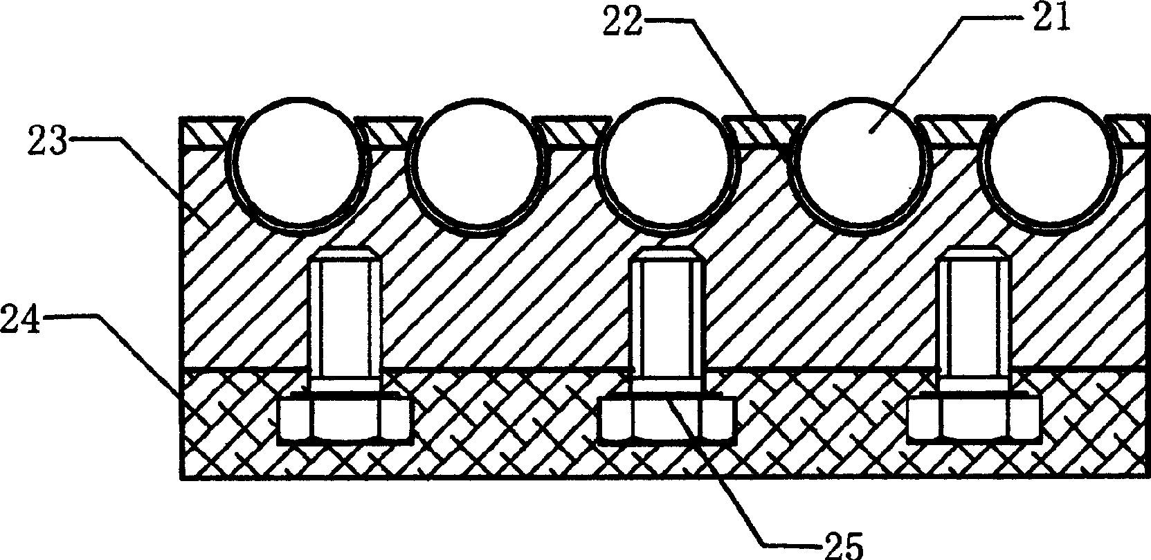
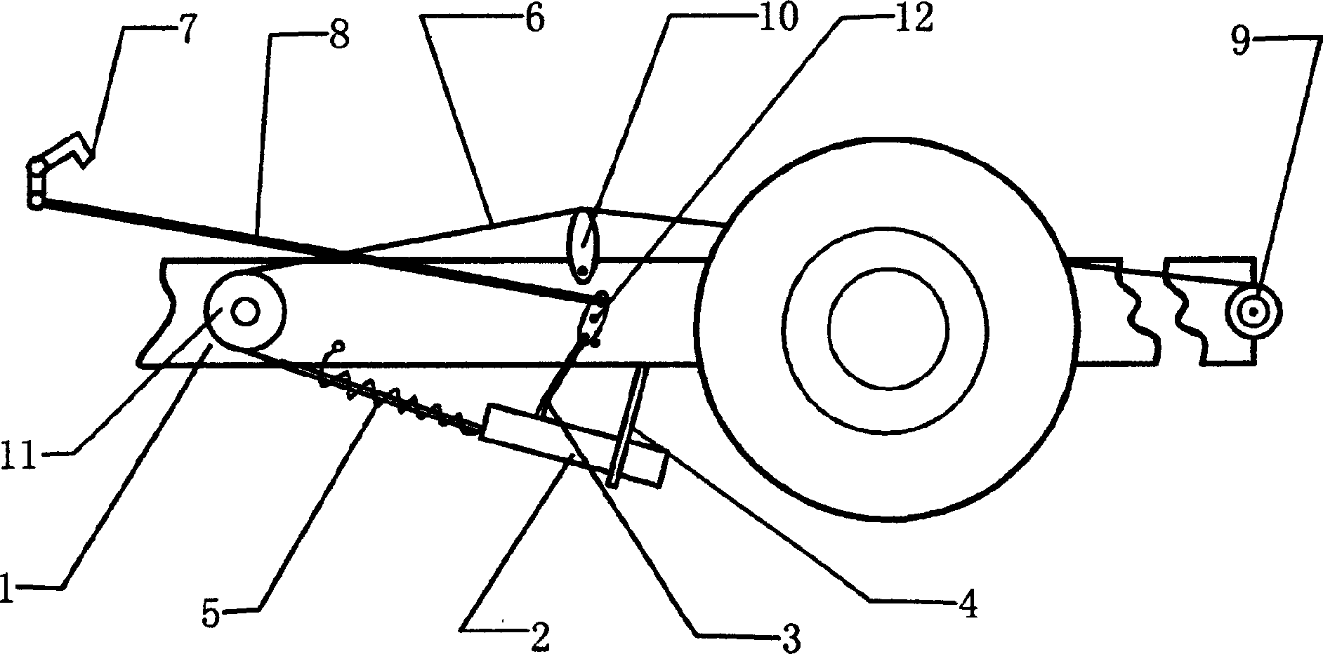
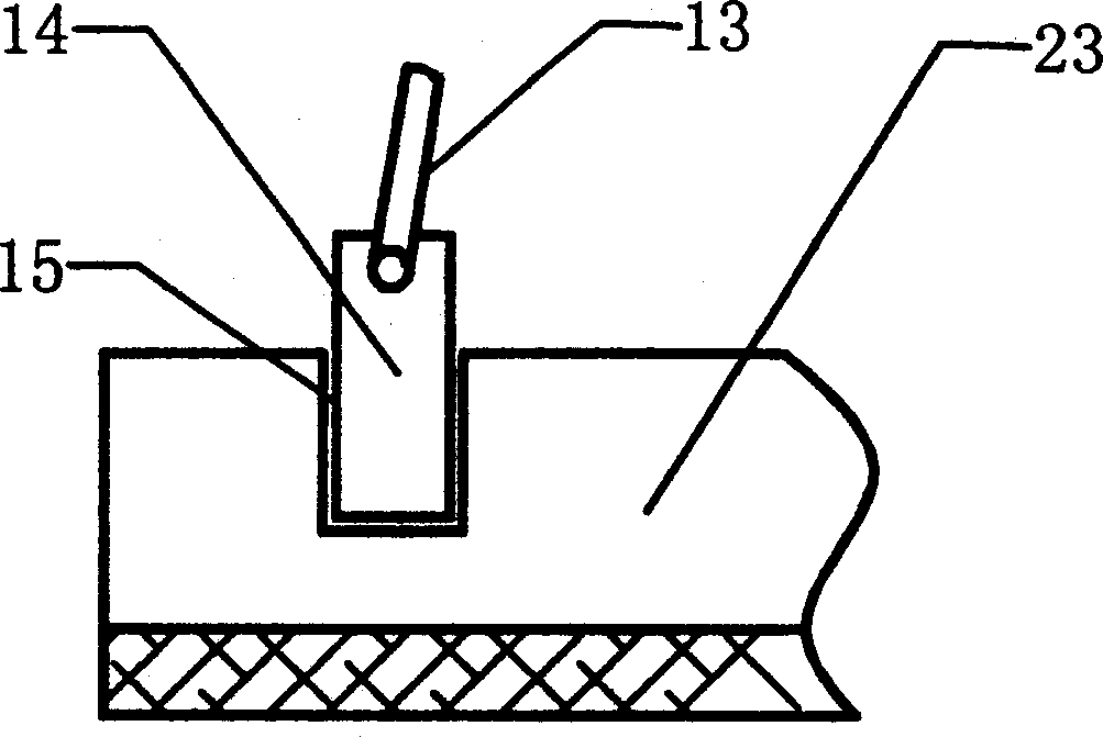
[0012] Such as figure 1 The shown brake pad includes a plate body, and a plurality of rolling bodies and fixed connection mechanisms corresponding to the rolling bodies are arranged on the upper surface of the plate body. The plate body is composed of a steel plate (23) and a rubber plate (24), the rubber plate (24) is fixed on the bottom surface of the steel plate (23), and the connection between them is reinforced by screws (25). The steel plate (23) and the rubber plate (24) are selected to form the plate body, mainly because the rubber plate (24) has a large friction coefficient with the ground, which can produce a good braking effect, and the steel plate (23) It can play a very good shaping effect, prevent the plate body from being deformed due to too much impact force during use, and provide guarantee for the normal operation of the rolling body. The rolling body is a steel ball (21), and the fixed connection mechanism is a groove (22) corresponding to the steel ball (2...


PUM


Abstract

A braking plate for car features its short braking distance, and is composed of a plate body, one or more rollers on the plate body, and the fixing structure of said rollers. Its using method is also disclosed. Its application method is also disclosed.

Description

Technical field [0001] The present invention relates to a brake component for a vehicle, and the invention also relates to a method of using the brake component. Background technique [0002] At present, when the vehicle brakes, it mainly relies on the wheels to be braked by its brake device, and then the sliding friction force generated by the wheels and the ground is used to achieve the purpose of braking. Because the contact surface between the wheel and the ground is small, the friction force generated is also small. Therefore, for a vehicle traveling at high speed, the sliding distance of the vehicle body after braking is relatively large. The distance is large and it is difficult to avoid the occurrence of a car accident. Contents of the invention [0003] In order to reduce and prevent car accidents, the brake component provided by the invention can reduce the sliding distance of the vehicle body after braking; therefore, the invention also provides a method for us...

Claims


Application Information

Patent Timeline
IPC IPC(8): B60T1/14
Inventor 唐云龙
Owner 唐云龙
Learn More