
Plane solar energy spotlight power supply module

A solar energy concentration and power module technology, applied in the field of solar cells, can solve the problems of planar solar cell modification, no further cost reduction, and unrealistic high investment, and achieve low tracking accuracy requirements, no difficulty, and low concentration rate Effect

Inactive Publication Date: 2003-12-10
JX CRYSTALS
View PDF0 Cites 20 Cited by
  • Summary
  • Abstract
  • Description
  • Claims
  • Application Information

AI Technical Summary

Problems solved by technology

The market share of this method is above 90%, but the cost has been reduced to the minimum, and there is no possibility of further cost reduction
[0005] The argument for the second method is that the cost of silicon wafers is too high, and it is necessary to manufacture a thin-film battery to reduce the cost
30% efficient solar cells are not currently produced by companies and investment is still needed
But this creates two problems: the first problem is that planar solar cells have to be significantly modified to work at 20 times the sun
The second problem is that planar solar cell suppliers are not motivated to cooperate, for example, if solar concentrating systems prove to be cheaper, and the market expands by 3 times
Moreover, the high investment required to manufacture a new battery in large quantities is unrealistic. Another problem to be solved is the connection problem between solar cells.

Method used


Image

  • Plane solar energy spotlight power supply module
  • Plane solar energy spotlight power supply module
  • Plane solar energy spotlight power supply module

Examples


Embodiment Construction

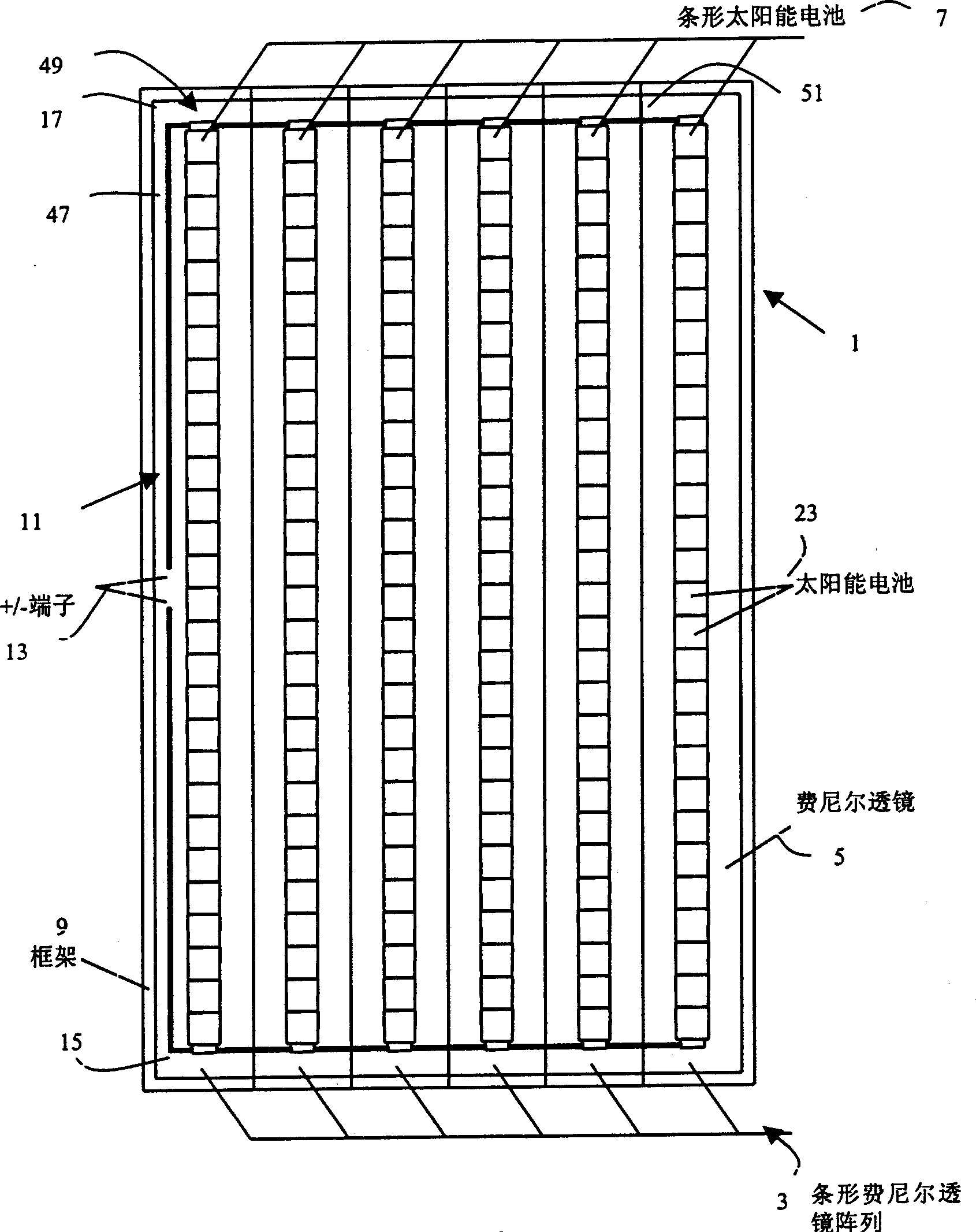
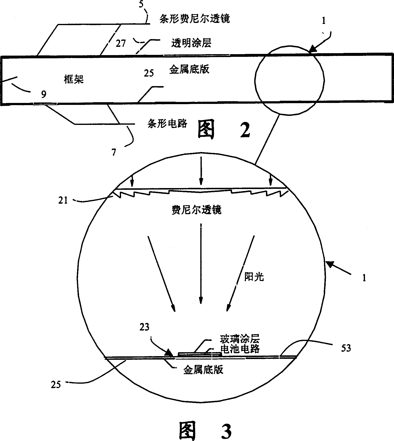
[0053] figure 1 , 2, 3, and 8 show a preferred planar solar concentrating power supply module 1 . figure 1 It is a top view of the planar solar concentrating module 1 of the present invention. An array 3 of strip-shaped Fresnel lenses 5 produces focused solar radiation that falls on an aligned strip-shaped photoelectric conversion circuit array. Figure 2 is figure 1 The cross section of the planar solar concentrator module 1 . The cross section is perpendicular to the focused rays produced by the lens and also perpendicular to the length of the circuit. FIG. 3 is a partially enlarged view of FIG. 2 , showing a single lens 21 and a circuit unit 23 in more detail.

[0054] The preferred device described is exemplary and the dimensions are not limited to the specifications given below. For example, a preferred device may be 25" x 40" x 3.25" (thick). The dimensions described are exemplary and are similar to 75W planar modules produced by Siemens, Kyocera, and Solarex. All of...


PUM


Abstract

A planar concentrator solar power module has a planar base, an aligned array of linear photovoltaic cell circuits on the base and an array of linear Fresnel lenses or linear mirrors for directing focused solar radiation on the aligned array of linear photovoltaic cell circuits. The cell circuits are mounted on a metal back plate. The cell circuit area is less than a total area of the module. Each linear lens or linear mirror has a length greater than a length of the adjacent cell circuit. The cell circuit may have cells mounted in shingle fashion to form a shingled-cell circuit. In an alternative module, linear extrusions on the circuit element have faces for mounting the linear mirrors for deflecting sun rays impinging on each mirror onto the shingled-cells. The linear extrusions are side-wall and inner extrusions with triangular cross-sections. The circuit backplate is encapsulated by lamination for weather protection. The planar module is generally rectangular with alternating rows of linear cell circuits and linear lenses or linear mirrors.

Description

[0001] This application claims the benefit of US Provisional Application Patent Nos. 60 / 374,808 (April 24, 2002) and 60 / 391,122 (June 25, 2002). technical field [0002] The invention relates to a solar cell, in particular to a planar solar concentrated power supply module. Background technique [0003] Solar cells generate electricity, but the cost is too high compared to the electricity produced by power plants. It is generally believed that the cost of solar panels must drop to about $1-$2 per watt before they can compete in the huge potential market. Today, solar panels cost in the $6-$7 per watt range. Three different approaches have been taken in trying to address the cost issue. [0004] The usual method is to lay a large number of solar silicon cells on a planar module, and the cell area in the module accounts for more than 80% of the entire flat panel area. The battery using this method can be a single crystal battery or a polycrystalline battery with large parti...

Claims


Application Information

Patent Timeline
Patent Type & Authority Applications(China)
IPC IPC(8): F24S23/30H01L31/0232H01L31/042H01L31/048H01L31/05H01L31/052H01L31/18
CPCY02E10/52F24J2/085H01L31/0504H01L31/042H01L31/0522H01L31/05H01L31/0232H01L31/02Y02E10/50F24S23/31
Inventor L·M·弗拉斯黄汉祥项守娟J·E·艾弗瑞
Owner JX CRYSTALS
Learn More