Image sensor assembly and its mfg. method

A technology of an image sensor and a manufacturing method, which is applied in the directions of image communication, instruments, electrical components, etc., can solve the problems of poor manufacturing efficiency of the image sensor assembly 100, blurred lens 101, unusable use, etc.

Inactive Publication Date: 2003-12-10
ROHM CO LTD
View PDF0 Cites 23 Cited by
  • Summary
  • Abstract
  • Description
  • Claims
  • Application Information

AI Technical Summary

Problems solved by technology

That is, at present, since the work of applying the adhesives 105, 107 is cumbersome, and it takes time for the adhesives 105, 107 to harden, the manufacturing efficiency of the image sensor module 100 is not good.
In order to improve manufacturing efficiency, although there are also cases where instant adhesives are used as the adhesives 105 and 107, due to the influence of the solvent contained in the instant adhesives, there is also a so-called inappropriate situation in which the lens 101 is blurred.
In addition, there are cases where the instant adhesive has a short pot life due to natural hardening, and cannot be used for a short period of time, resulting in an increase in cost.

Method used


Image

  • Image sensor assembly and its mfg. method
  • Image sensor assembly and its mfg. method
  • Image sensor assembly and its mfg. method

Examples


Embodiment Construction

[0023] Refer below Figure 1~5 , to describe in detail the preferred embodiments of the present invention.

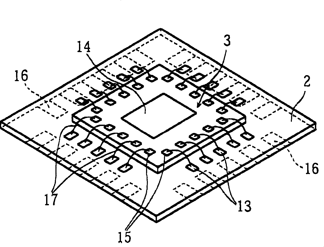
[0024] figure 1 An image sensor module according to one embodiment of the present invention is shown. The illustrated image sensor assembly X mainly includes a first lens A; a second lens B; a frame-like holder 1 for holding the two lenses A and B; a substrate 2; and an image sensor chip 3 mounted on the substrate 2 Bracket 4, the bracket 4 is arranged between the holder 1 and the base plate 2.

[0025] The first lens A includes a lens portion A1 formed at a middle portion thereof and a flat edge portion A2 surrounding the periphery of the lens portion A1. Also, the second lens B includes a lens portion B1 formed in a middle portion thereof and a flat edge portion B2 surrounding the periphery of the lens portion B1. These lens portions A1 , B1 converge the light traveling from the object to be photographed, and the image of the object to be photographed is formed o...


PUM


Abstract

An image sensor module includes a holder and a lens unit attached in the holder. The lens unit is held in the holder by at least one engagement projection formed by plastically deforming a part of the holder. Preferably, the lens unit includes a first lens spaced from the engagement projection and a second lens adjoining the engagement projection. Each of the first lens and the second lens includes a central lens portion, and a flat peripheral portion surrounding the lens portion. The flat peripheral portion of the first lens is held in contact with the flat peripheral portion of the second lens. The engagement projection engages the flat peripheral portion of the second lens.

Description

technical field [0001] The present invention relates to an image sensor module used in a digital camera, a mobile phone with a camera, etc., and a manufacturing method thereof. Background technique [0002] Past image sensor assemblies have features such as Figure 6 structure as shown. Specifically, the illustrated image sensor assembly 100 includes a lens 101 and a holder 102 . The lens 101 is used for converging light traveling from a subject to be photographed to an image sensor chip 104 mounted on a substrate 103 . The holder 102 supports and protects the lens 101, and the lens 101 is fitted therein. In order to fix and hold the lens 101 , the peripheral portion of the lens 101 is bonded to the holder 102 with an adhesive 105 . In addition, the holder 102 is bonded with an adhesive 107 to a frame 106 on which the substrate 103 is attached at the bottom thereof. [0003] In the conventional image sensor module 100 described above, there are disadvantages as follows. ...

Claims


Application Information

Patent Timeline
Patent Type & Authority Applications(China)
IPC IPC(8): G02B7/02G02B13/00H04N5/225H04N5/335H04N5/372H04N5/374
CPCH04N5/2254H04N5/2257G02B13/006G02B7/021H04N23/57H04N23/55
Inventor 藤本久义大西弘朗
Owner ROHM CO LTD
Why Eureka
Try Eureka