Commutator motor

A commutator, motor technology, applied in the direction of DC commutator, electric components, electromechanical devices, etc., can solve problems such as increasing the output level of magnetic sensors

Inactive Publication Date: 2003-10-29
FUNAI ELECTRIC CO LTD
View PDF1 Cites 1 Cited by
  • Summary
  • Abstract
  • Description
  • Claims
  • Application Information

AI Technical Summary

Problems solved by technology

[0011] The present invention has been designed to overcome the above-mentioned drawbacks, and its purpose is to provide a commutator motor that can generate FG signals without making the shape larger and more complicated in structure, so that the magnetic sensor for generating FG signals can be increased output level, even when the output level increases, simplifying the installation of magnetic sensors

Method used


Image

  • Commutator motor
  • Commutator motor
  • Commutator motor

Examples


Embodiment Construction

[0036] Referring now to the accompanying drawings, a description will be given of specific embodiments of the present invention.

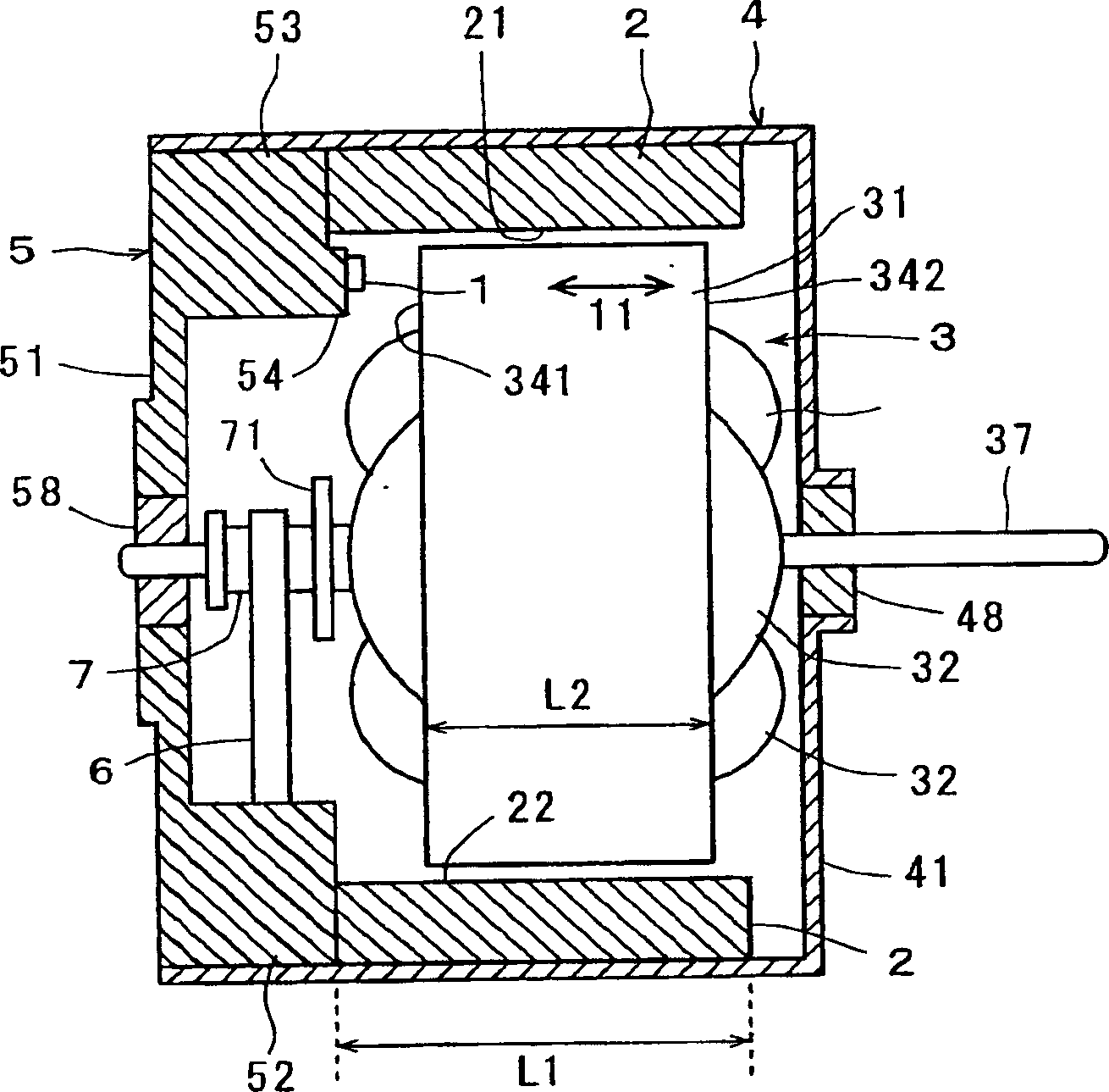
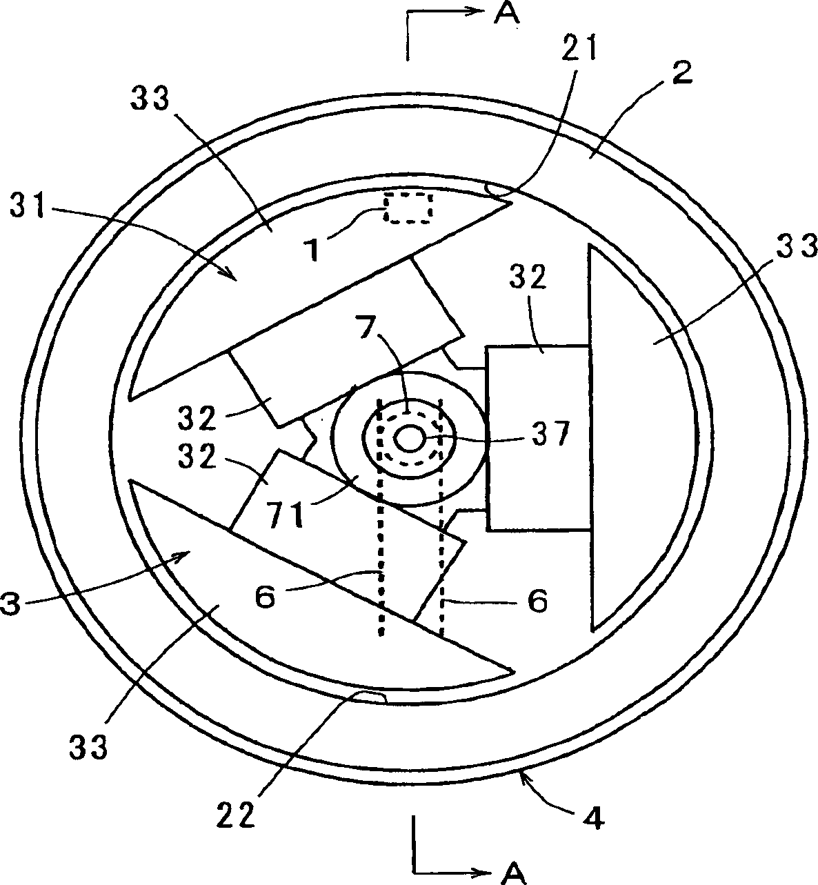
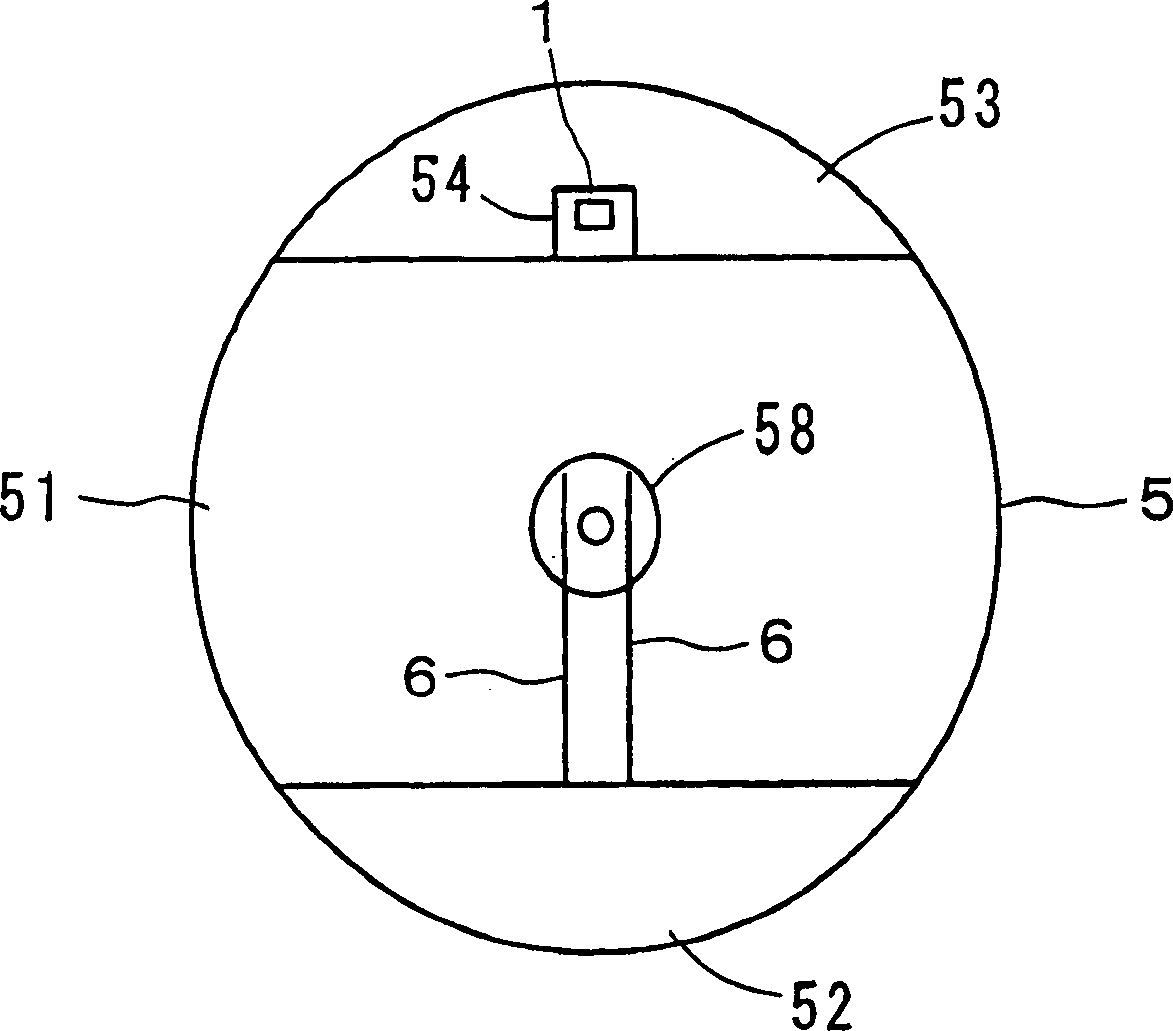
[0037] Figure 1A and Figure 1B is a block diagram illustrating a first embodiment of the commutator motor according to the present invention. Figure 1B shows the shape seen from the rear of the commutator motor, while Figure 1A shows along the Figure 1B A cross-sectional view taken along line A-A of ; in addition, figure 2 It is a shape drawing of the end frame plate seen from the inside.

[0038] In the drawing, an annular permanent magnet 2 for forming a field magnet is fixed to the inner periphery of a substantially cylindrical motor case 4 whose one end portion is closed. The rotor 3 is rotatably supported by a bearing 58 provided on the end frame plate 5 , and a bearing 48 is provided on the disc-shaped front plate 41 of the motor case 4 . The rotor 3 has a rotor core 31 fixed to a motor shaft 37 , and the rotor core 31 has three a...


PUM


Abstract

A commutator motor has a magnetic sensor for detecting changes in field magnets that occur in response to changes in the rotational position of a rotor core.

Description

[0001] This application is related to subject matter included in Japanese Patent Application No. 2002-114316 filed Apr. 17, 2002, the entirety of which is incorporated herein by reference. technical field [0002] The present invention relates to a commutator motor provided with a magnetic sensor for detecting changes in field magnets corresponding to changes in the rotational position of the rotor core. Background technique [0003] A frequency generator (hereinafter referred to as FG) is used in the detection of the rotational speed of the DC motor. In the case of a brushless motor, a configuration has been proposed in which a sensor such as an FG coil for detecting a magnetic field from a rotating permanent magnet is provided (JP-UM-B-4-48145). However, in the case of a commutator motor, since the permanent magnet does not rotate, it has not been proposed in the conventional technique disclosed in JP-UM-B-7-13420. [0004] That is, in this technique, there is provided a ...

Claims


Application Information

Patent Timeline
Patent Type & Authority Applications(China)
IPC IPC(8): H02K11/00H02K23/66
CPCH02K23/66H02K11/215
Inventor 樋口善男
Owner FUNAI ELECTRIC CO LTD
Why Eureka
Try Eureka