
Steel support frame

A technology for steel brackets and steel components, which is applied in the field of steel brackets, and can solve problems such as lengthening of drilling or screwing work, disengagement of screws, and weakening of structural strength.

Inactive Publication Date: 2003-10-22
方仁昌
View PDF0 Cites 3 Cited by
  • Summary
  • Abstract
  • Description
  • Claims
  • Application Information

AI Technical Summary

Problems solved by technology

[0004] However, the problem with existing steel brackets is that the longitudinal and transverse steel members are joined to the strut members or components by multiple screws that can come loose over time and their structural strength can be weakened
In addition, another problem with the above-mentioned steel bracket is that it is necessary to tighten a plurality of screws at the corresponding contact portions of the steel member and the column member, so that the work of drilling or screwing is significantly lengthened.

Method used


Image

  • Steel support frame
  • Steel support frame
  • Steel support frame

Examples


Embodiment Construction

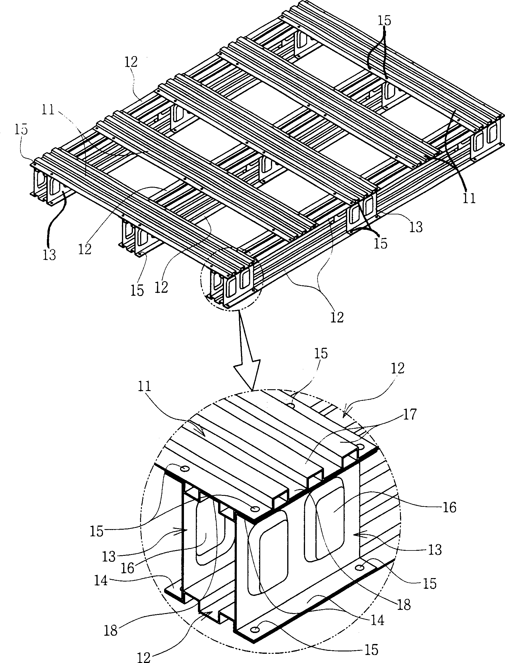
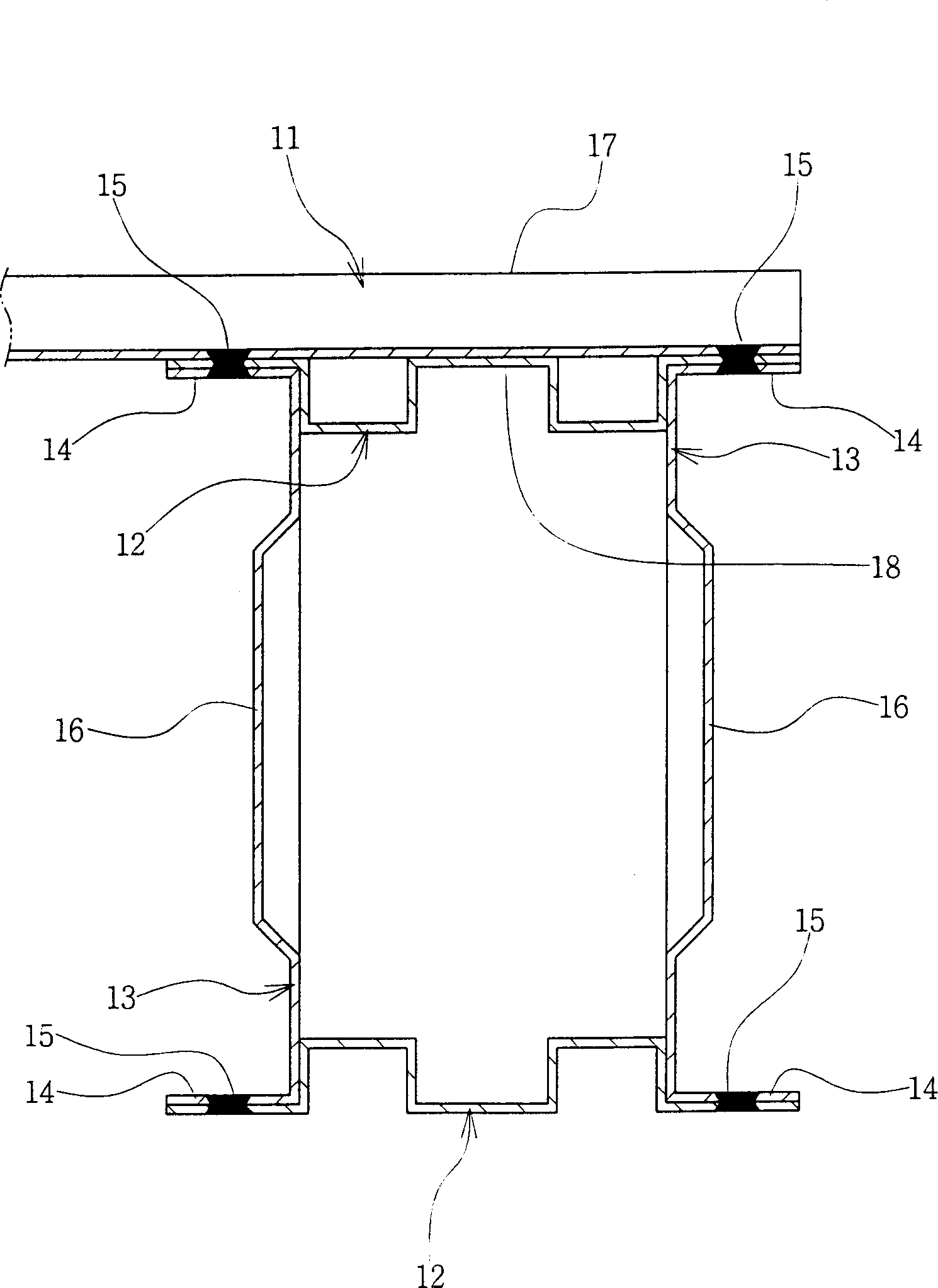
[0009] A preferred embodiment of the present invention will be described in detail below with reference to the accompanying drawings. Wherein, Fig. 1 is a structural view of a preferred embodiment of the present invention, figure 2 It is a partially enlarged cross-sectional view of this embodiment. As shown in these figures, the steel bracket 1 of the present invention includes an upper plate 2 and a plurality of strut members 13 fixed to the upper plate 2 by spot welding 15 .

[0010] The upper panel 2 is manufactured by combining a plurality of transverse steel members 11 and a plurality of longitudinal steel members 12 in a cross pattern. Here, the longitudinal and transverse members 11 , 12 are made of corrugated steel plates formed by folding the steel plates so as to alternately form recesses 18 and protrusions 17 . Also, the column member 13 is constituted by a pair of channel members 13a, 13b having a C-shaped cross section having flanges 14 at upper and lower ends. ...


PUM


Abstract

The present invention relates to a steel bracket. According to one aspect of the present invention, the steel bracket includes an upper support plate which has crossing patterns formed by a horizontal steel member and a vertical steel member and plurality of support members fixed on the lower surface of the upper support plate. Wherein, the support member is sulciform member with C shape section and has flanges at two end parts. The overlap part of the flanges of the support members, the horizontal steel member and the vertical steel member are welded together, thereby the three members can combine together through a common welding point. The steel bracket of the invention has high structure intensity and durability, and can simplify the manufacturing technics, thereby reduce the cost and improve the productivity significantly.

Description

technical field [0001] The present invention relates to a steel bracket which is structurally robust and allows considerably reduced manufacturing effort and costs. Background technique [0002] The pallet is a support plate used to load and lift up goods by an elevator in loading and unloading goods or transporting goods. In the prior art, wooden or plastic pallets have been used. The problem with wooden brackets, however, is that they are structurally weak and because they are made of expensive wood, they are more expensive. In addition, the wooden pallet is not suitable for international trade because it causes a problem of preventing infectious diseases due to the proliferation of harmful bacteria or harmful insects. In addition, the plastic bracket has problems in that a large metal mold is required in manufacture, and its structural strength is not satisfactory. [0003] Therefore, a steel bracket made of a steel plate such as a galvanized steel plate has recently b...

Claims


Application Information

Patent Timeline
Patent Type & Authority Applications(China)
IPC IPC(8): B65D19/28
CPCB65D19/00
Inventor 方仁昌
Owner 方仁昌
Learn More