
Developer apparatus and image forming apparatus

A technology of developing equipment and developer, which is applied in the fields of electrical recording process equipment, electrical recording technology, optics, etc., which can solve the problems of cost increase, electric field distribution change, voltage supply circuit complexity, etc., and avoid circuit structure. Effects of complexity, improved stability, and no increase in cost

Inactive Publication Date: 2003-10-15
SHARP KK
View PDF0 Cites 2 Cited by
  • Summary
  • Abstract
  • Description
  • Claims
  • Application Information

AI Technical Summary

Problems solved by technology

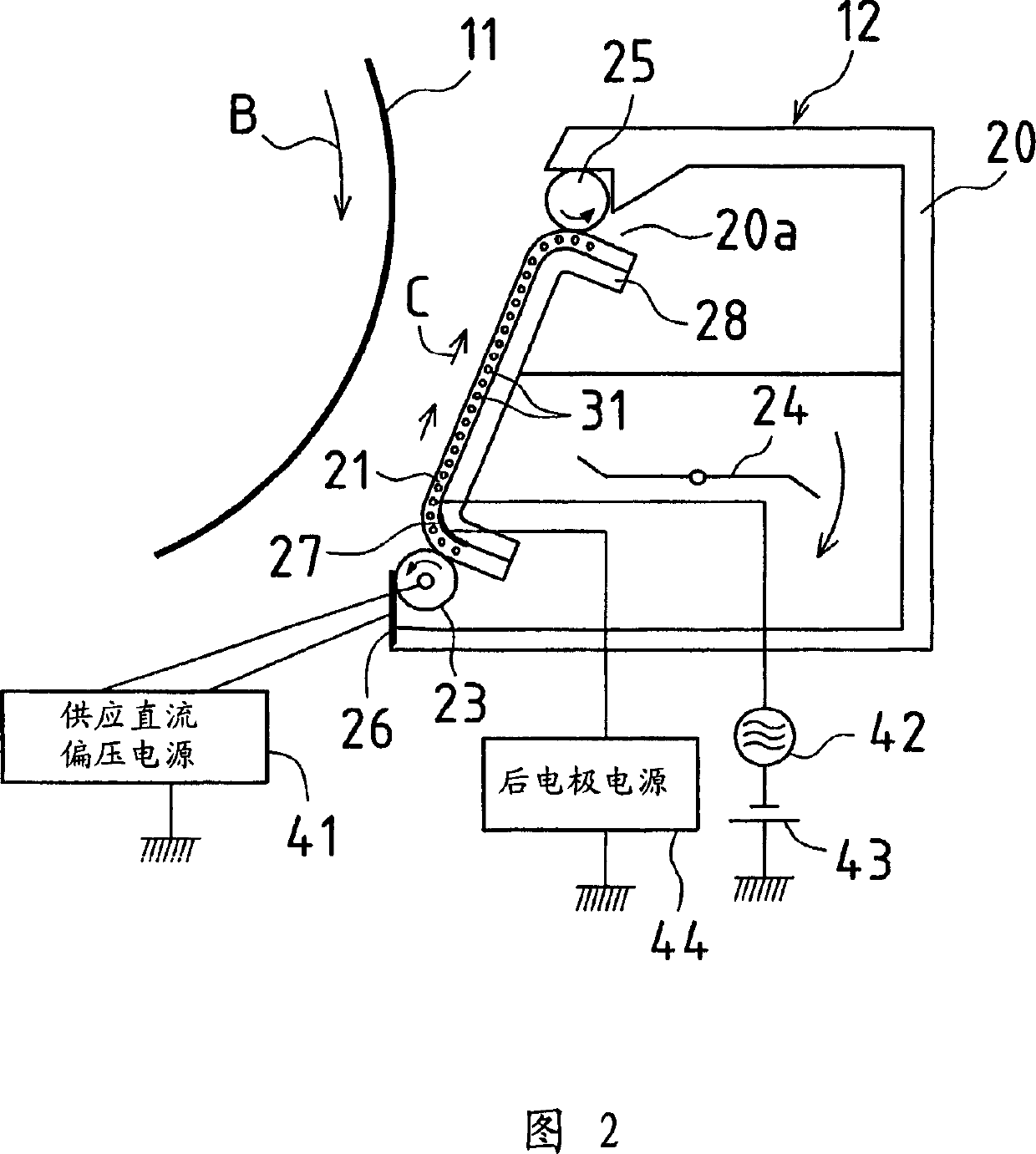
Therefore, in addition to complicating the voltage supply circuit with additional equipment in the form of mechanism for changing the respective AC high voltages, since it is necessary to maintain the stable operation of the voltage supply circuit, the maintenance of stable operation and the mechanism for changing the respective AC high voltages inevitably increase the cost
[0010] In addition, the DC bias voltage Vd on the developer material supply member is changed as shown in FIG. DC bias on components such as auxiliary supply elements that smoothly supply developer material, again complicating and increasing the cost of the voltage supply circuits used to supply these DC voltages
In addition, since changes in the respective DC bias voltages on these elements will lead to changes in the electric field distribution near the developer material transport path, it may cause undesired behavior or affect the developer material transport during the development process.

Method used


Image

  • Developer apparatus and image forming apparatus
  • Developer apparatus and image forming apparatus
  • Developer apparatus and image forming apparatus

Examples


Embodiment Construction

[0050] Preferred embodiments of the present invention will be described in detail below with reference to the accompanying drawings.

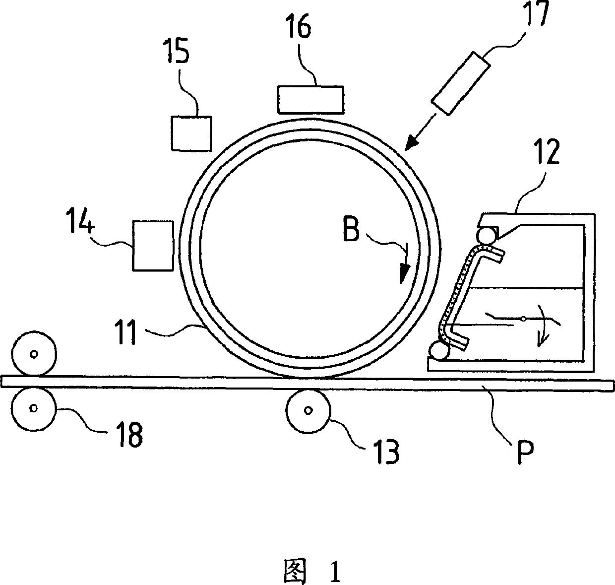
[0051] Fig. 1 is a side view schematically showing an image forming apparatus representing an embodiment of a developing apparatus according to the present invention. This image forming device forms an image using electrophotographic technology, and the developing device 12, transfer device 13, cleaning device 14, charge removing device 15, charging device 16, exposing device 17, etc. surround the photosensitive device in order from a certain upstream point in the direction of rotation. Drum 11 is set. In addition, the fixing device 18 is provided at a certain point downstream in the conveying direction of the recording paper P. As shown in FIG.

[0052] In the image forming apparatus of this embodiment, as the photosensitive drum 11 rotates in the direction indicated by the arrow B, the surface of the photosensitive drum 11 is uniformly charg...


PUM


Abstract

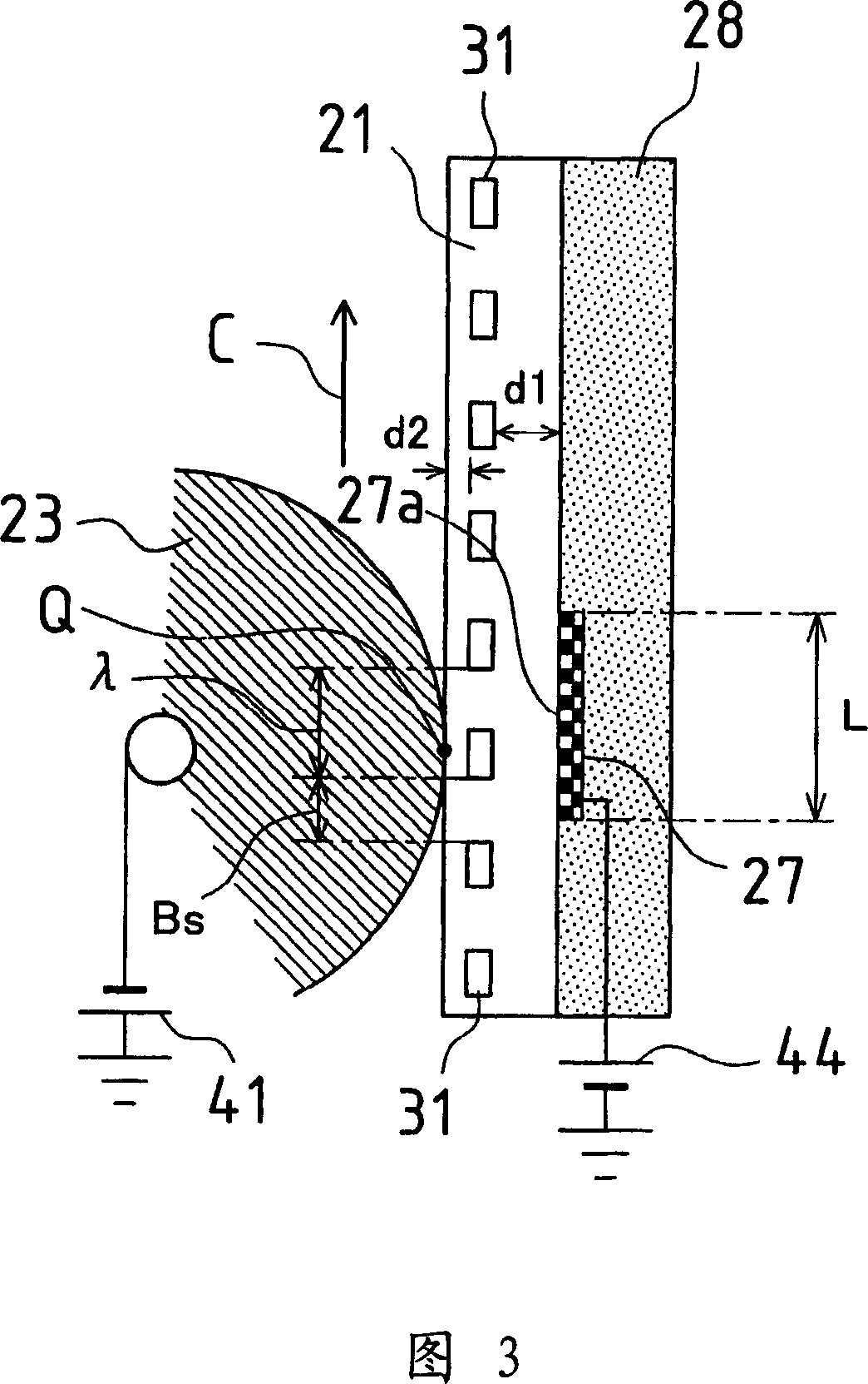
The invention discloses a developer apparatus and image forming apparatus. Rear electrode(s) 27 is or are arranged at location(s) at the back(s) of toner transport path(s) 21 opposite supply roller(s) 23, and rear electrode(s) 27 is or are moreover embedded in support(s) 28, toner-supplying voltage(s) from rear electrode power supply or supplies 44 being applied to rear electrode(s) 27, toner-supplying electric field(s) being formed in the vicinity or vicinities of supply roller(s) 23, toner-supplying voltage(s) from rear electrode power supply or supplies 44 being varied as appropriate, and intensity or intensities of toner-supplying electric field(s) being adjusted so as to permit increased stability in toner supply amount(s).

Description

technical field [0001] The present invention relates to a developing device and an image forming device in which a developer material is transported by a traveling wave electric field, and an electrostatic latent image is developed with the developer material. Background technique [0002] In the field of copiers, printers, and other image forming apparatuses employing electrophotography, developing apparatuses using a non-contact method in which a developer material is delivered to the vicinity of an image carrier, and the developer material is cast onto the image carrier On the electrostatic latent image above, the electrostatic latent image is developed. Such non-contact methods include a powder cloud method, a jumping method, and a method using an electric field curtain (traveling electric field). [0003] A method using a traveling wave electric field has been described, for example, in Japanese Laid-Open Patent Publications Heisei H5-31146 (1993) and Heisei H5-31147 (...

Claims


Application Information

Patent Timeline
IPC IPC(8): G03G15/08
CPCG03G15/08G03G2215/0643
Inventor 足立克己佐久间将实
Owner SHARP KK
Learn More