Deflection current modulating circuit
A technology of deflecting current and modulating voltage, which is applied in TV, electrical components, color TV, etc., and can solve problems such as damped oscillation at the top of the image
- Summary
- Abstract
- Description
- Claims
- Application Information
AI Technical Summary
Problems solved by technology
Method used
Image
Examples
Embodiment Construction
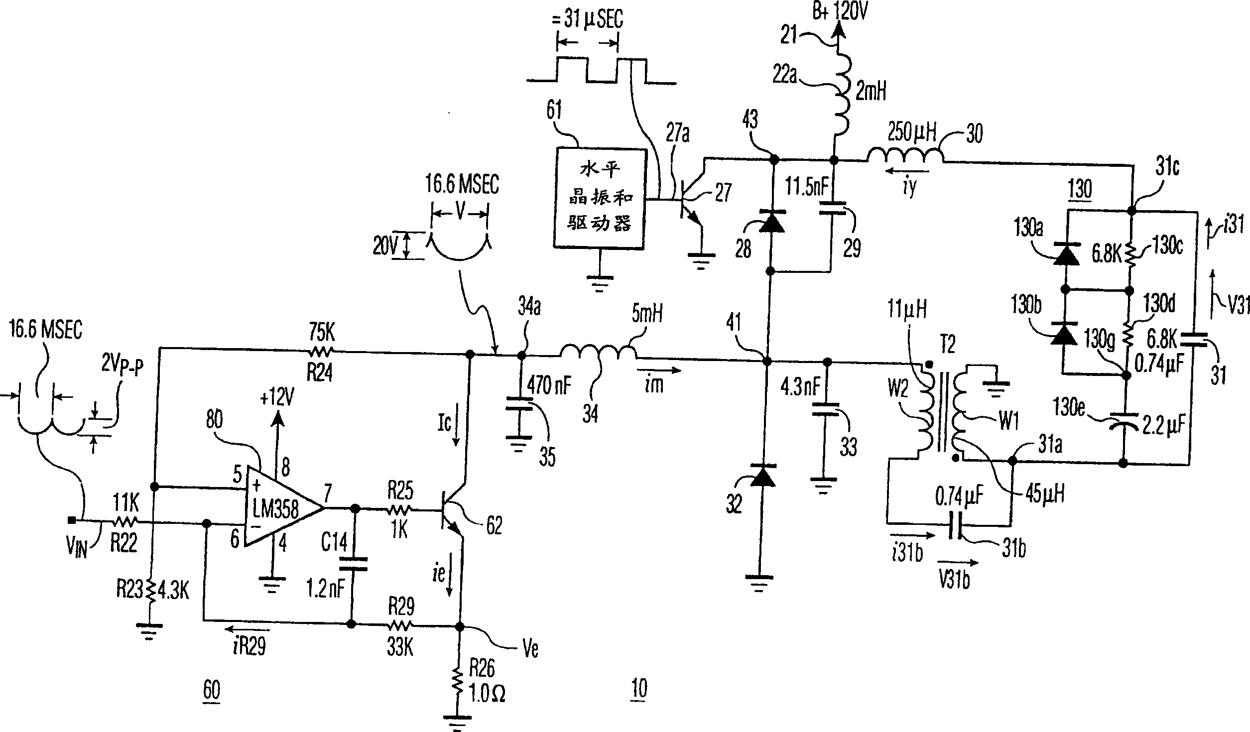
[0009] figure 1 A horizontal deflection circuit 10 embodying one aspect of the invention is illustrated. An operating voltage B+ is developed at one end 21 of the power coil 22a. Coil 22a is coupled to collector terminal 43 of conventional horizontal output transistor 27 . The base of transistor 27 is coupled to receive drive signal 27a from conventional horizontal sum driver stage 61 having a horizontal rate of 31,468 Hz and a corresponding period H.
[0010] Also coupled to terminal 43 is a series connection of horizontal deflection coil 30, first retrace or S capacitor 31 and coil W1 of interlead correction transformer T2. Ringing suppression network 130 is formed by diode 130 a and diode 130 b coupled in series between terminal 31 c and terminal 130 g of capacitor 31 . The ringing suppression network 130 also includes a resistor 130c and a resistor 130d coupled in parallel to the diode 130a and the diode 130b, respectively. Ringing suppression network 130 also includes...
PUM
 Abstract
Description
Claims
Application Information
 - R&D Engineer
- R&D Manager
- IP Professional
- Industry Leading Data Capabilities
- Powerful AI technology
- Patent DNA Extraction
Browse by: Latest US Patents, China's latest patents, Technical Efficacy Thesaurus, Application Domain, Technology Topic, Popular Technical Reports.
© 2024 PatSnap. All rights reserved.Legal|Privacy policy|Modern Slavery Act Transparency Statement|Sitemap|About US| Contact US: help@patsnap.com


