Diaphragm pump

A diaphragm and pump body technology, applied in the field of diaphragm pumps, can solve the problems of unfavorable manufacturing and assembly costs, complex structure, etc., and achieve the effect of simple structure

Inactive Publication Date: 2003-07-23
REXAM SMT
View PDF0 Cites 4 Cited by
  • Summary
  • Abstract
  • Description
  • Claims
  • Application Information

AI Technical Summary

Problems solved by technology

[0003] Unfortunately, these pumps required the use of metal springs to return the compression device to the high position, and complex suction and discharge valves that used additio...

Method used


Image

  • Diaphragm pump
  • Diaphragm pump
  • Diaphragm pump

Examples


Embodiment Construction

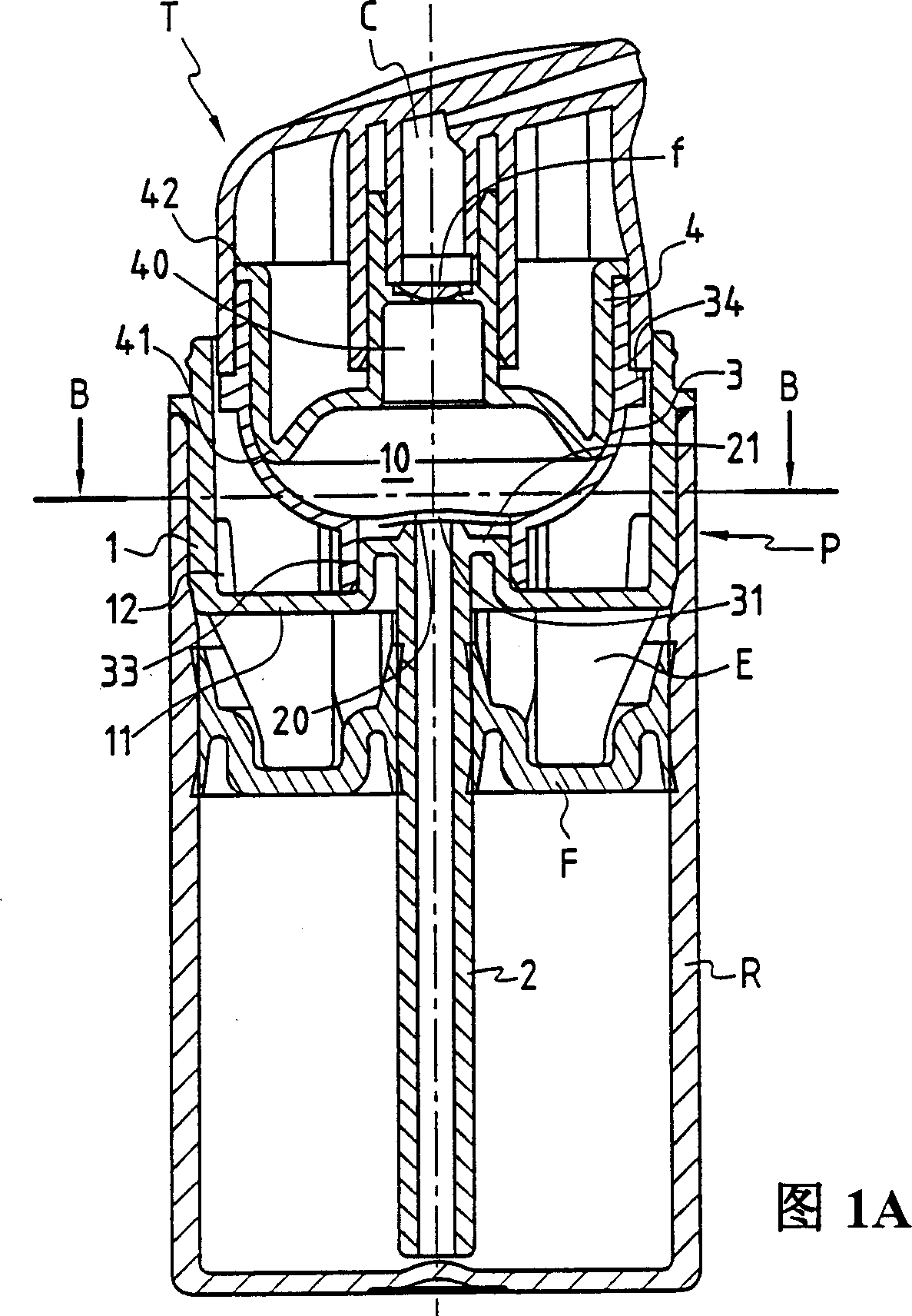
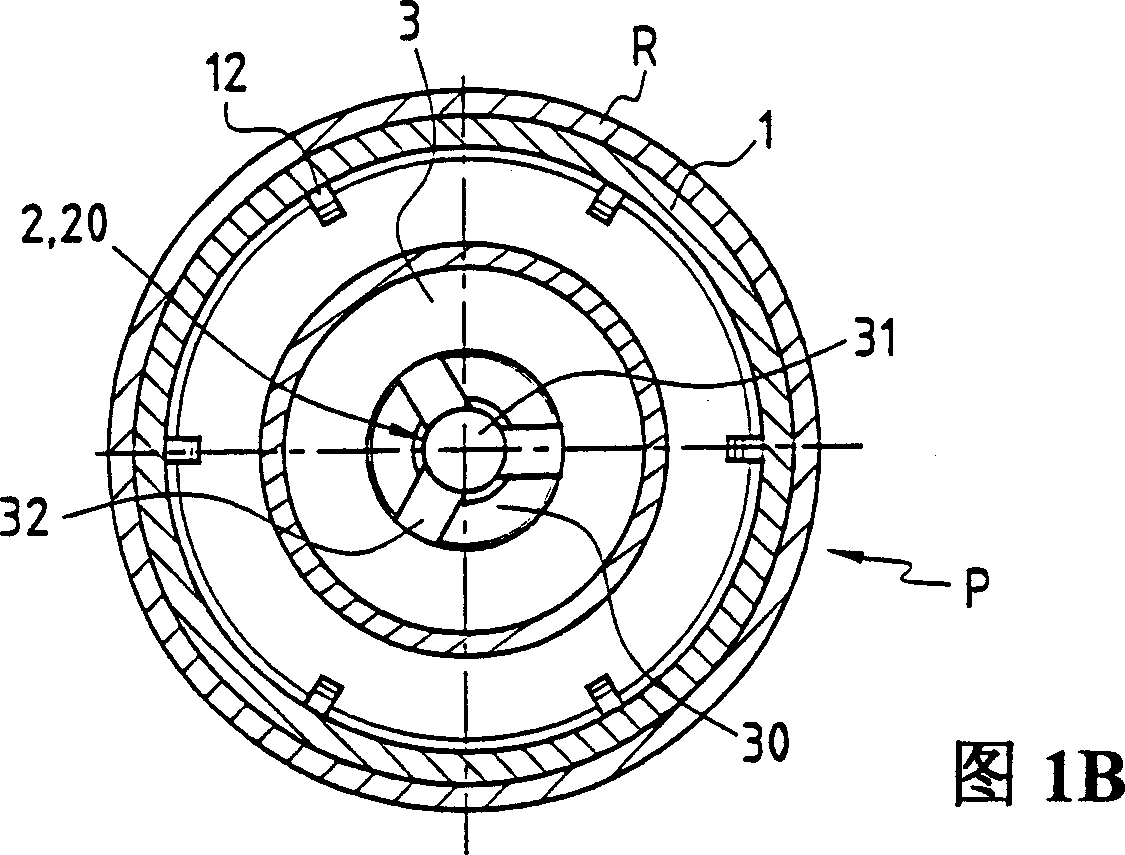
[0024] The pump P of the present invention shown in FIGS. 1A and 1B is used for dispensing a fluid or semi-fluid material in a container R .

[0025] The pump shown is of the "airless" type, that is, it has no air inlet and is therefore fitted with a movable partition F which both confines the contents of container R and scrapes the inner walls of the container.

[0026] During the continuous dispensing phase, the partition F in this example is adapted to move downwards from a high position where the container R is full, as shown in Figure 1A.

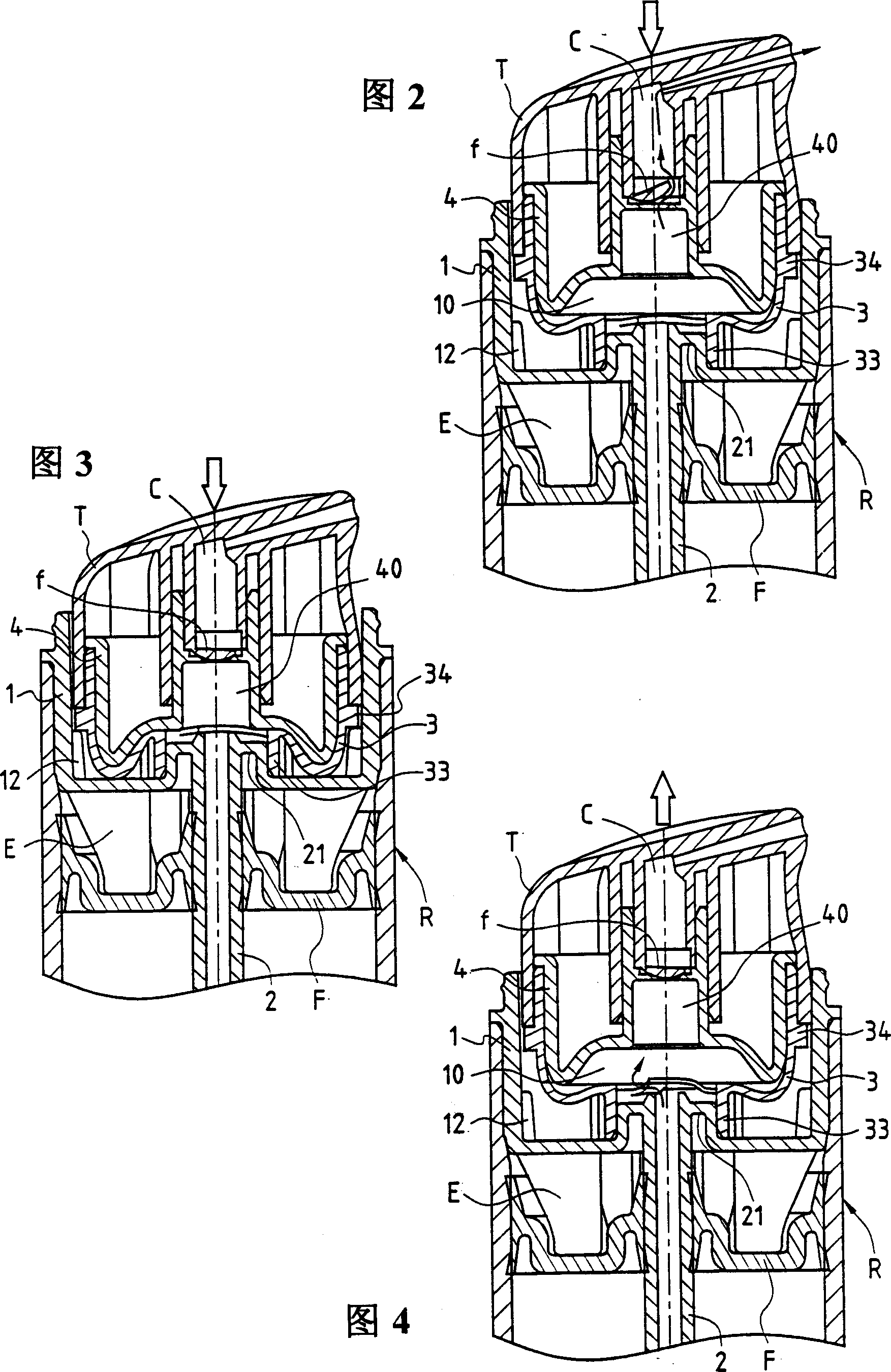
[0027] The pump P consists of a pump body 1, the pump body has a bottom, the bottom is connected with the immersion pipe 2 through the suction valve, the immersion pipe 2 is inserted into the material, the top of the pump body is connected with the top edge of the container R, when the container R is full, There is a pad E in the pump body 1 to prevent the movable partition F from moving upward.

[0028] The pump body 1 comprises a me...


PUM


Abstract

The invention provides a pump comprising a body (1) designed to communicate in its lower part with a dip tube (2) through an intake valve and to be connected in its upper part to the rim of a reservoir (R) and containing a metering chamber (10) sealingly closed in its upper part with compression means provided with an outflow valve and a return member capable of being actuated by manual pressure on a dispensing head (T) and provided with a discharge duct (C). The invention is characterised in that said return member comprises an elastically deformable inner diaphragm (3) borne by the dispensing head (T) and co-operating with a rigid cup (4) fixed beneath the head (T) and defining with said diaphragm (3) the metering chamber (10).

Description

technical field [0001] The invention relates to a pump, in particular to a diaphragm pump. Background technique [0002] In general form, conventional pumps consist of a pump body having a bottom connected to the immersion tube via a suction valve and a top connected to the side of the container, the pump itself including a metering chamber via a The discharge valve and the compressing means of the return element are closed in a sealed manner at the top, and the pump is adapted to be driven by a manual push acting on a dispenser head equipped with a delivery tube. [0003] Unfortunately, these pumps require the use of a metal spring to return the compression device to the high position and also require the manufacture of complex suction and discharge valves using additional metal elements such as balls. [0004] As a result, these pumps consist of a large number of parts made of various materials, which is disadvantageous both in terms of manufacturing and assembly costs. ...

Claims


Application Information

Patent Timeline
IPC IPC(8): B65D47/20B05B11/00B65D47/34F04B9/14F04B43/02
CPCB05B11/3028B05B11/0051B05B11/029B05B11/1028
Inventor E·罗西尼奥尔
Owner REXAM SMT
Why Eureka
Try Eureka