Magnetic controlled foot ball game appliance

A technology for game consoles and football, applied in indoor games, sports accessories, etc., can solve problems such as visual distortion of the table surface, which is not conducive to fair competition in games

Inactive Publication Date: 2003-07-16
吕耀海
View PDF0 Cites 10 Cited by
  • Summary
  • Abstract
  • Description
  • Claims
  • Application Information

AI Technical Summary

Problems solved by technology

Players are directly fixed on the rotating rods exposed on the table, which makes the table visually distorted. After the ball is in the net,

Method used


Image

  • Magnetic controlled foot ball game appliance
  • Magnetic controlled foot ball game appliance
  • Magnetic controlled foot ball game appliance

Examples


Embodiment Construction

[0008] The present invention will be further described below in conjunction with specific embodiments.

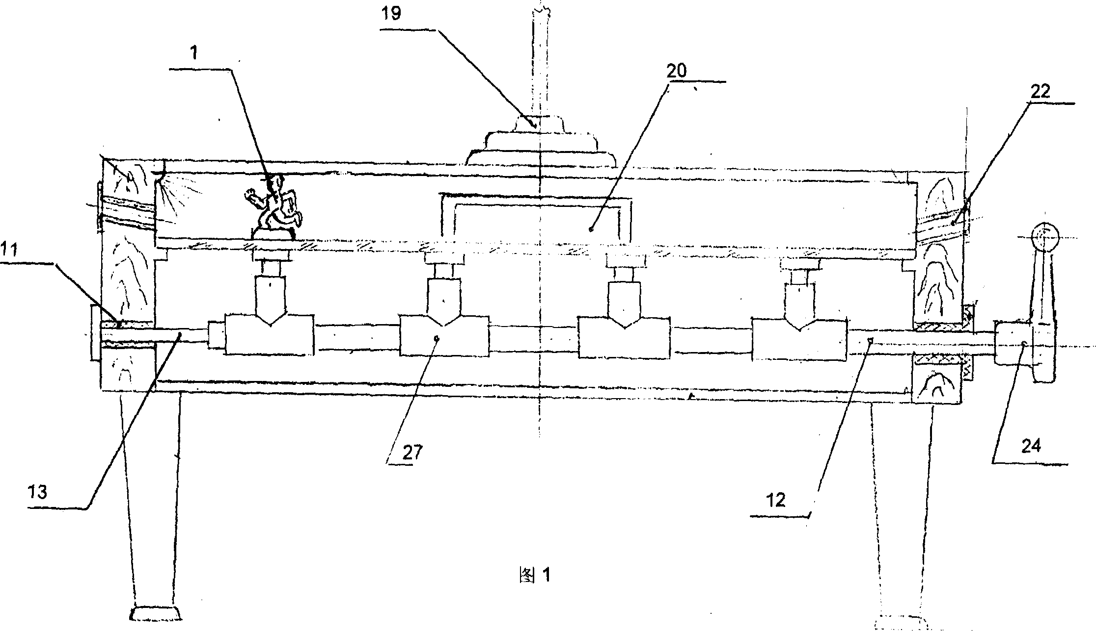
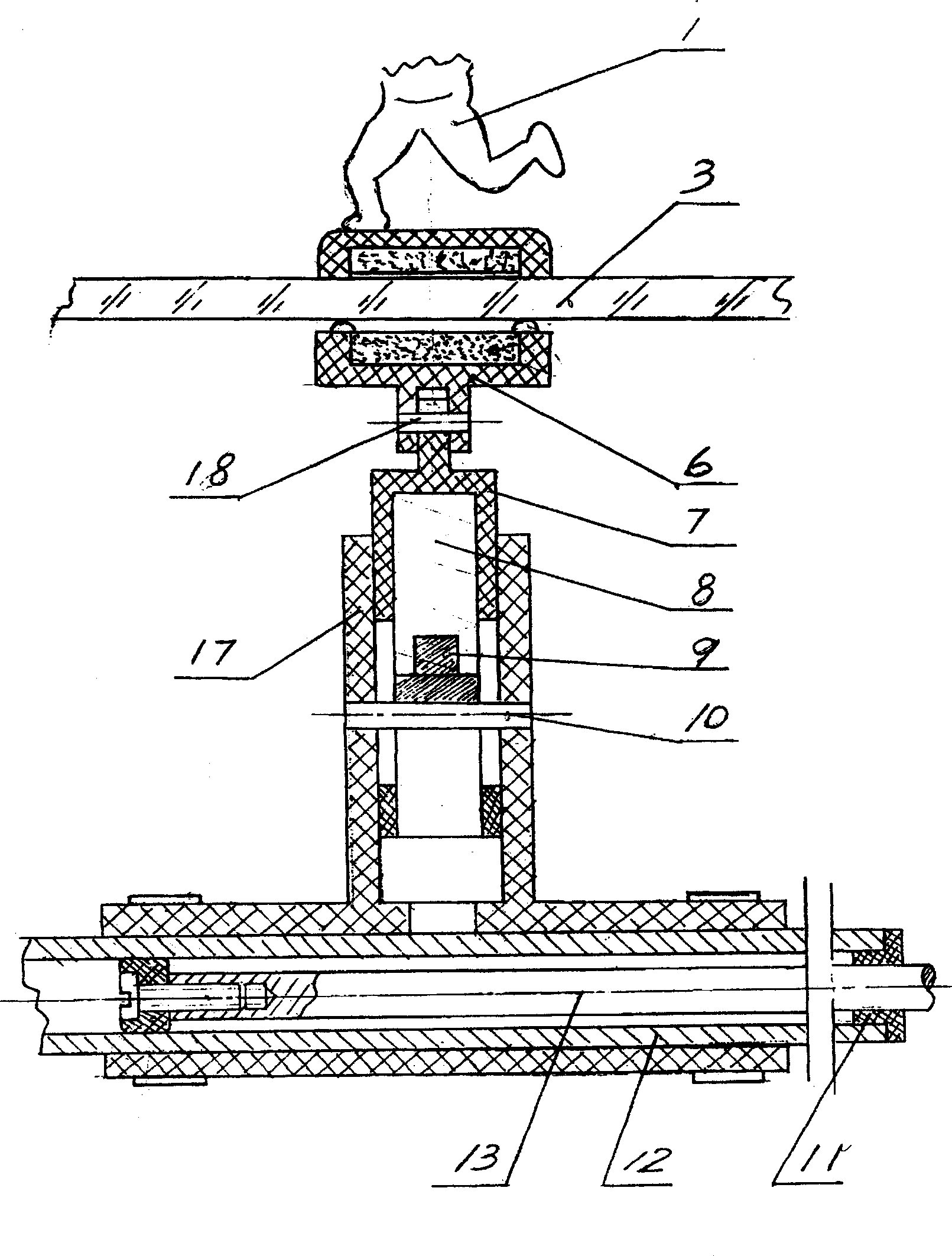
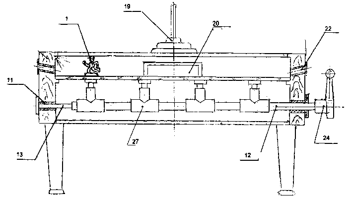
[0009] figure 1, figure 2 The shown magnetic control football game machine is made up of magnetron 27, control bar 12, ball table 3 and player 1, and described magnetron is made up of sliding swing core 7, spring pressure column 9, spring 8, swing bar 17, The spring 8 is loaded into the sliding swing core 17, pressed in by the spring pressure column 9, and put into the swing rod 17 together, aligning with the long grooves on both sides of the sliding swing core and inserting the sliding pin 10, so that the sliding swing core can only move along the swing rod. Sliding, the magnetic box 6 and the sliding swing core are connected by a rotating pin 18, so that the magnetic box can rotate around the pin 18; the control rod 12 is sleeved on the fixed rod 13 fixed on the fixed sleeve 11, and the handle 24 is connected with the control rod; the chronograph Branch circuit is instal...


PUM


Abstract

A magnetically controlled football game machine is composed of magnetic controllers fixed to telescopic control rods, control rods under a table, football game table, football players arranged in serveral lines on the table and controlled by magnetic controllers on the control rods, goals on the table, and electronic score unit.

Description

1. Technical field [0001] The present invention relates to a gaming device. 2. Background technology [0002] The football game machines currently in use are all directly exposed manual rotating rods in structure. The Zhuancun exposed at the other end will be strung in and out, and it is very easy to stab the player on the opposite side of the table. Players are directly fixed on the rotating rods exposed on the table top, which makes the table top visually distorted. After the ball is in the net, the ball is directly taken out from the net to serve. There is no timing and scoring device, which is not conducive to fair competition in the game. 3. Contents of the invention [0003] The object of the present invention is to provide a football game machine, which can prevent the player from being stabbed by the handle, has a realistic table top, is equipped with an electronic timing and time-limiting device, and has a ball scoring loop. [0004] In order to achieve the abov...

Claims


Application Information

Patent Timeline
IPC IPC(8): A63F7/06
Inventor 吕耀海
Owner 吕耀海
Why Eureka
Try Eureka