
Multifunctional integrated power virtual test analysis method and its test analysis apparatus

A technology of virtual testing and analysis methods, applied in the field of test instruments, can solve the problems of complicated wiring, large workload, unable to meet special requirements well, and achieve the effect of large amount of information and easy operation

Inactive Publication Date: 2003-07-09
申明 +1
View PDF0 Cites 34 Cited by
  • Summary
  • Abstract
  • Description
  • Claims
  • Application Information

AI Technical Summary

Problems solved by technology

[0004] (1) There are many types of measuring meters for each test, the wiring is complicated, and the workload is large
[0005] (2) Since the measurement data of various meters are manually recorded, multiple people are required to work at the same time, resulting in poor consistency of the measurement data, and the manual reading error is large, and the accuracy requirements of the measurement results cannot be guaranteed
[0006] (3) For the test record results, whether it is manually drawing and sorting the report or inputting the recorded data into the computer for drawing and report sorting, the analysis of the test results will be time-consuming and laborious, and the work efficiency will be low
Therefore, the data display and curve restoration of this type of digital test and analysis instrument have no real-time performance, and the test personnel have to wait until the end of the test to see the test process curve
At the same time, due to the hardware limitation of the front-end single-chip microcomputer, the data recording capacity of this type of digital test and analysis instrument cannot be very large
[0010] (3) It is not easy to expand the function of this kind of special digital test and analysis instrument, it is difficult to upgrade, and it cannot well meet some special requirements put forward by users in field use

Method used


Image

  • Multifunctional integrated power virtual test analysis method and its test analysis apparatus
  • Multifunctional integrated power virtual test analysis method and its test analysis apparatus
  • Multifunctional integrated power virtual test analysis method and its test analysis apparatus

Examples


Embodiment 1

[0112] Example 1, such as Figure 31 It is a schematic diagram of an embodiment of testing the no-load characteristics of a generator.

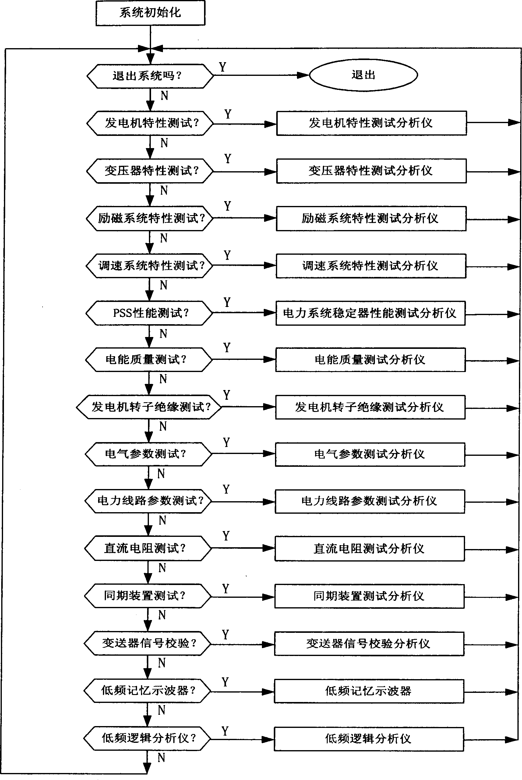
[0113] First, the generator three-phase stator voltage (V3, V4, V5), generator rotor excitation voltage V1, generator rotor excitation current V2 (expressed by the voltage on the shunt), exciter current A1 and other signals are used as input signal A1 Connect to input interface module 2. Then the operator operates the instrument function selector 8 through the input keyboard of the man-machine interface processor 5 to select the generator characteristic test analyzer 9 . After the input signal (AI) is pre-processed by the input interface module 2 for isolation, filtering, matching, and correction, it is then sent to the signal conversion module 3 for A / D conversion and data acquisition, and then sent to the computer motherboard 1 for information processing. and result analysis and calculation, and then on the liquid crystal display terminal...

Embodiment 2

[0114] Example 2, such as Figure 32 It is a schematic diagram of an embodiment for calibrating a voltmeter.

[0115] First, the output voltage of the output interface module 4 is connected to the voltmeter (V) as an output signal (AO). The operator operates the instrument function selector 8 through the input keyboard of the man-machine interface processor 5 to select the transmitter signal calibration analyzer 20 . The operation interface of the transmitter signal calibration analyzer 20 is as follows: Figure 23 shown. On the operation interface, set the type knob to the DC position, press the voltage signal key (U), set the amplitude knob to a certain voltage value, and press the "output 1" button. At this time, the computer motherboard 1 calculates and Generate corresponding output data, and send the data to the signal conversion module 3 for D / A conversion, and then send it to the output interface module 4 for power amplification, and then output the voltage to the ex...

Embodiment 3

[0116] Example 3, such as Figure 33 It is a schematic diagram of an embodiment of performing a DC resistance test on a transformer coil winding.

[0117] First, the DC output current of the output interface module 4 is inserted into the transformer (T) coil winding (current A) as an output signal (AO), and then the DC voltage V in the transformer (T) coil winding is used as an input signal ( AI) is input into the input interface module 2. The operator operates the instrument function selector 8 through the input keyboard of the man-machine interface processor 5 to select the DC resistance test analyzer 18 . Select the DC output current value on the operation interface of the DC resistance test analyzer 18, and the current value data is sent to the signal conversion module 3 by the computer mainboard 1 for D / A conversion, and then sent to the output interface module 4 for power amplification. A current (A) is generated and applied to the transformer (T) coil windings. The v...


PUM


Abstract

The present invention relates to a multifunctional integrated power virtual testing analysis method, and is characterized by that the computer hardware resource and its matched input interface, output interface, signal conversion, communication interface, printing interface and human-machine interface module and application seftware package made up according to the coulometric working mechanism of several tested objects are formed into a computer-operated modularized instrument virtual testing system. Said invention utilizes different application software packages to implement coulometric test analysis of tested object under the support of same hardware. Its working control machine is formed from computer main board containing CPU and memory, input interface module, output interface module, signal conversion module.

Description

technical field [0001] The invention relates to a test instrument mainly used for characteristic test and analysis of various electrical equipment in a power system, in particular to a multifunctional comprehensive power virtual test and analysis method and a test analyzer designed according to the method. Background technique [0002] With the wide application of computer technology in various control processes of generator sets, higher requirements are put forward for the measurement of various electrical parameters of generator sets. Not only the measurement signals are required to be comprehensive, accurate, reliable, and real-time, but also real-time Record the change track of various parameters in the control process to obtain the best control parameters. However, at present, it is still mainly used in the generator set characteristic test, transformer characteristic test, excitation system characteristic test, speed control system characte...

Claims


Application Information

Patent Timeline
IPC IPC(8): G01R31/00G01R31/34
Inventor 申明胡嘉纯
Owner 申明
Learn More