Luminous diode illuminating light source device

A technology of light-emitting diodes and lighting sources, applied in lighting devices, parts of lighting devices, lighting and heating equipment, etc., can solve the problems of being unable to be effectively used for lighting, not easy to produce in large quantities, falling off, etc., to facilitate automatic assembly, Improved accuracy and high mass production

Inactive Publication Date: 2003-07-02
IND TECH RES INST
View PDF2 Cites 12 Cited by
  • Summary
  • Abstract
  • Description
  • Claims
  • Application Information

AI Technical Summary

Problems solved by technology

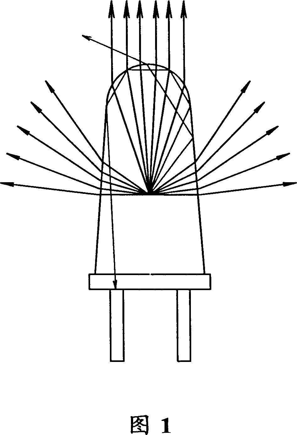
[0003] Generally, LED lighting sources use a plurality of LED bulbs arranged in a planar array, in which there are light-emitting diodes inside to generate radiant light, part of the radiant light goes to the top of the bulb and passes through the convex lens, refracted into slightly parallel upward light, and The four sides of the surrounding light are greater than the critical angle of total reflection, or the light that is bent to the side at a large angle cannot be effectively used for lighting. Figure 1 shows the light collection situation of the traditional light bulb. It can be seen that the light collection effect is still improved space
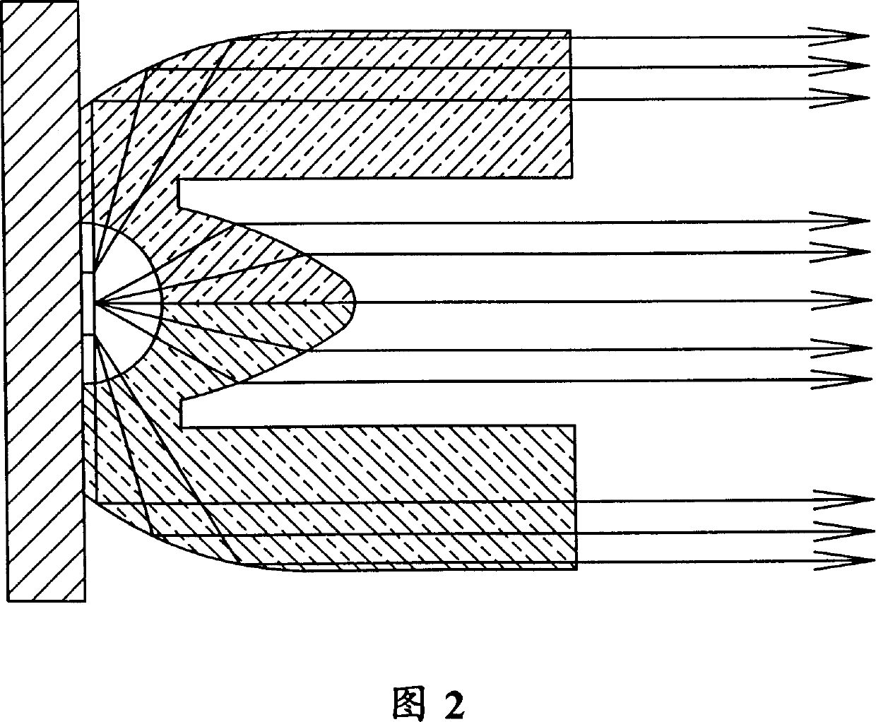
For example, in the patent of US4767172, referring to Figure 2, the organic light emitting diode needs to pass through the air and then through the lens. Protection and fixation, there is a problem of delamination under long-term temperature changes; the base area of ​​the lens is also small, so the vertical accuracy of the optical axis attached to the substrate is not easy to be high
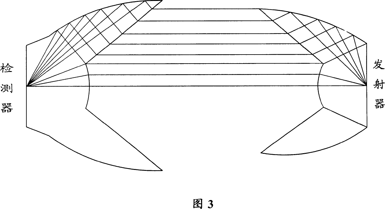
For example, the light-emitting diode light-collecting design proposed by David in 1986 (US4770514 patent case), as shown in Figure 3, the bottom area of ​​the optical component attached to the substrate is small, and the optical axis is not easy to align; and the reflective film is exposed on the outside. It will gradually fall off with temperature changes for a long time; in terms of production, the organic light-emitting diode of the patent US4770514 does not cooperate with automatic design, and it is not easy to mass produce

Method used


Image

  • Luminous diode illuminating light source device
  • Luminous diode illuminating light source device
  • Luminous diode illuminating light source device

Examples


Embodiment Construction

[0017] The present invention provides a light-emitting diode lighting source device, as shown in Figure 4-1, which is a schematic diagram of the light-emitting diode device of the present invention, and its structure mainly includes a substrate 1, a reflector platform 2, a concave basin reflector 3, a lens 4, Optical axis 5, LED grain 6, substrate optical axis positioning hole 7, convex lens 8, mirror optical axis positioning hole 9.

[0018] The substrate 1 can carry the light-emitting diode crystal grain 6 and the reflector platform 2. The shape of the reflector platform 2 can be square or hexagonal, and can be gathered together in a square or honeycomb arrangement; each reflection The mirror platform 2 can have a plurality of concave basin reflectors 3, the central bottom surface of the concave basin reflector 3 is hollow and the bottom surface of the hollow part is flatly attached to the substrate 1. Particle 6, and the concave part of the concave basin mirror 3 is a parab...


PUM


Abstract

An LED equipment as light source for lighting features that the light from each of LEDs on bottom plate is refracted by convex lens, reflected upward by sorrounded concave reflector, and refracted by the cone around the convex lens to make the light beams in same direction.

Description

technical field [0001] The invention relates to a light-emitting diode lighting source device, most of which are used for lighting in a limited area, and can be applied to indoor night lights, display lighting, flashlights, outdoor traffic sign lights, vehicle lights, billboards, etc. Background technique [0002] In order to provide high-efficiency, power-saving and long-life lighting devices, light-emitting diodes have gradually replaced traditional light bulbs. However, the large-angle light sources emitted by light-emitting diodes require higher light-collecting components to be suitable for small-angle lighting applications, such as indoor night lights and flashlights. , Display lighting, outdoor traffic sign lights, vehicle lights, billboards and other small-area lighting needs. [0003] Generally, LED lighting sources use a plurality of LED bulbs arranged in a planar array, in which there are light-emitting diodes inside to generate radiant light, part of the radiant ...

Claims


Application Information

Patent Timeline
Patent Type & Authority Applications(China)
IPC IPC(8): F21V5/00F21V7/06F21V7/22F21V13/04
Inventor 韩伟国陈秋伶许荣宗
Owner IND TECH RES INST
Why Eureka
Try Eureka