
Porous body, its producing process & foaming apparatus used for the same production

A manufacturing method and a foaming device technology, which can be applied to other household appliances, applications, ceramic products, etc., and can solve the problem that other coal ash cannot be used.

Inactive Publication Date: 2003-06-04
MITSUBISHI HEAVY IND LTD +1
View PDF1 Cites 6 Cited by
  • Summary
  • Abstract
  • Description
  • Claims
  • Application Information

AI Technical Summary

Problems solved by technology

Furthermore, since there are more than ten types of coal used as a boiler fuel, even if the manufacturing conditions for a certain type of coal ash are found out, it cannot be used for other coal ash.

Method used


Image

  • Porous body, its producing process & foaming apparatus used for the same production
  • Porous body, its producing process & foaming apparatus used for the same production
  • Porous body, its producing process & foaming apparatus used for the same production

Examples


Embodiment Construction

[0042] embodiment of the invention

[0043] Embodiments of the manufacturing method of the porous body of the present invention and the foaming apparatus used for the manufacturing thereof will be described below using the drawings, but the present invention is not limited to the following embodiments.

[0044] [First embodiment]

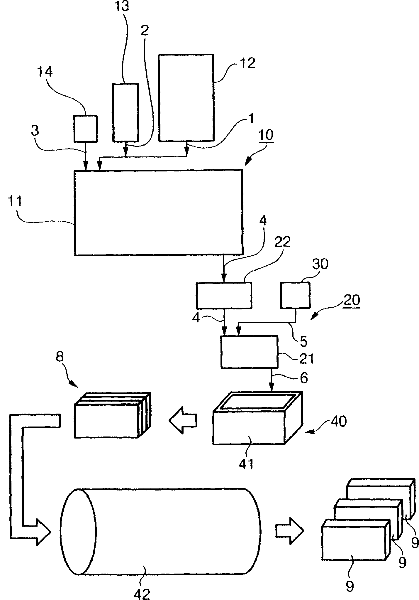
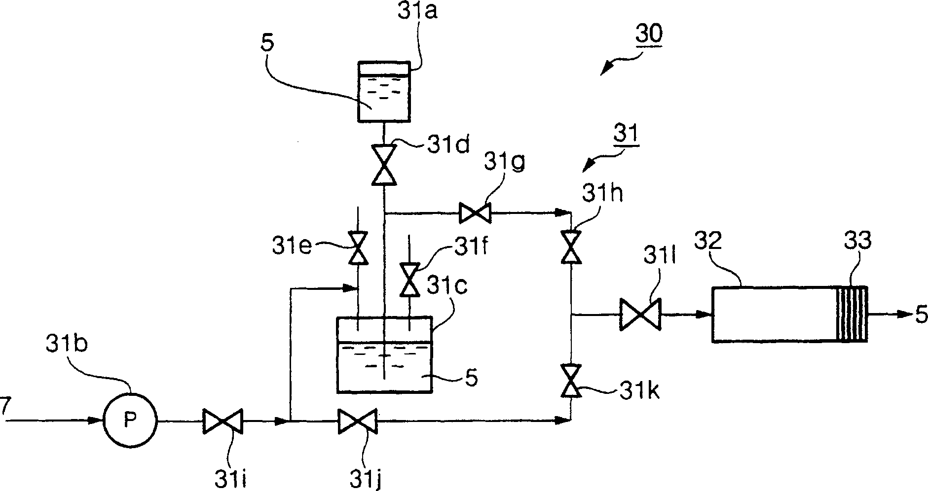
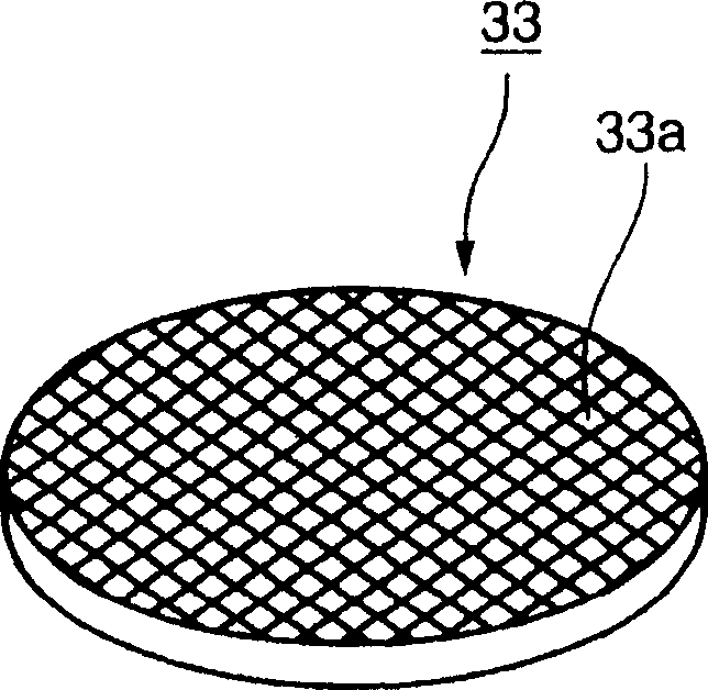
[0045] The first embodiment of the manufacturing method of the porous body of the present invention and the foaming device used in the manufacturing adopts Figure 1~3 Be explained.figure 1 It is a schematic diagram of the overall configuration of the porous body manufacturing device, figure 2 It is a schematic diagram of the composition of the foaming device, image 3 It is a schematic diagram of the structure of the mesh body.

[0046]

[0047] Such as figure 1 As shown, the porous body manufacturing apparatus of this embodiment has: a main raw material slurry manufacturing apparatus 10 that mixes the main raw materials of fly ash 1 and cem...


PUM

PropertyMeasurementUnit
Apertureaaaaaaaaaa
Viscosityaaaaaaaaaa
Densityaaaaaaaaaa

Abstract

The invention provides a process of producing a porous body which exhibits sufficient strength although it is obtained by using fly ash as a main component. The porous bodies 9 are obtained by feeding fly ash 1, cement 2 and water 3 from respective feeders 12-14 of a main raw material slurry producing unit 10 into a mixer 11, then mixing the raw materials to prepare a main raw material slurry 4 having a viscosity of 200-1,200 cp, feeding the main raw material slurry 4 from a feeder 22 of a foamed slurry production unit 20 to a mixer 21, at the same time, feeding a protein-based foaming agent from a foaming unit 30 into the mixer 21, after stirring for producing a foamed slurry 6, pouring the foamed slurry 6 into a molding flask 41 of a porous body forming unit 40 so as to cast, subjecting to preliminary steam curing, removing a cured material from the molding flask 41, cutting the formed body 8 removed from the mold into pieces each having a predetermined size using a piano wire, and curing the pieces in a curing unit 42.

Description

[0001] Field of invention [0002] The present invention relates to a porous body containing fly ash, its production method and a foaming device for the production. Background technique [0003] In Japan, about 60% of the large amount of coal ash and other fly ash generated from thermal power plants can be reused, but the remaining about 40% cannot be reused and must be disposed of in landfills. This is because the chemical composition and particle size distribution are different depending on the production area of ​​the coal used, and the quality of the fly ash (specific surface area (particle size) and unburned component amount (carbon amount), etc.) is dispersed due to the power output during power generation. That is to say, at present, when overseas coal is mainly used, it is used in the form of powder raw materials, and the variation in properties is large, and it is difficult to meet the conditions for manufacturing stable products. [0004] In addition, most of the re...

Claims


Application Information

Patent Timeline
IPC IPC(8): C04B18/08C04B28/02C04B38/00C04B38/02
CPCY02W30/91
Inventor 角田英雄田实洋一一瀬利光植田胜征籏崎裕章穐山泰治伊崎数博
Owner MITSUBISHI HEAVY IND LTD
Learn More