Waveguide display

A display and waveguide technology, which is applied in the field of manufacturing flat panel displays, can solve the problems of easy blocking of light

Inactive Publication Date: 2003-05-21
CAMBRIDGE FLAT PROJECTION DISPLAY
View PDF2 Cites 15 Cited by
  • Summary
  • Abstract
  • Description
  • Claims
  • Application Information

AI Technical Summary

Problems solved by technology

But in this application, the p...

Method used


Image

  • Waveguide display
  • Waveguide display
  • Waveguide display

Examples


Embodiment Construction

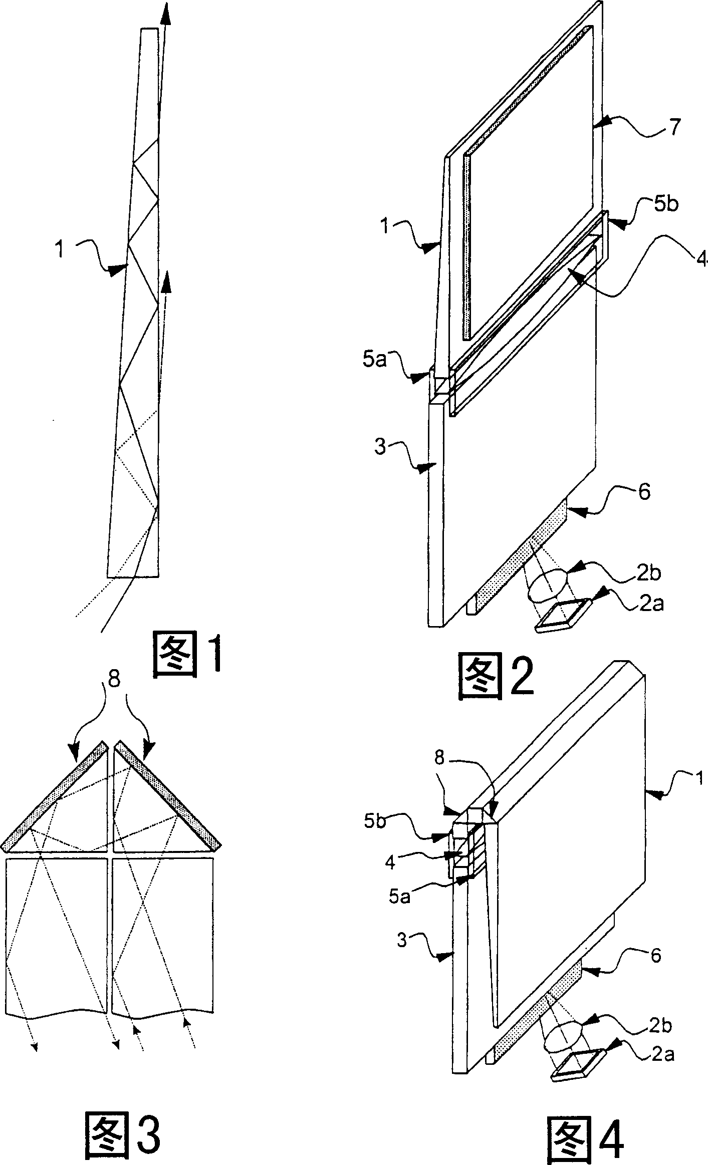
[0026] It is well known that a ray striking a cuboid plate made of transparent material at a sufficiently small out of plane angle will be reflected back and forth at the sides of the cuboid by total internal reflection until the ray reaches the opposite end from which it was incident . The ray is said to be guided, the slab of material is called the waveguide, and the out-of-plane angle of the ray remains constant as it propagates through the waveguide.

[0027] But if a ray is injected into the thick end of a tapered waveguide as shown in Figure 1, the out-of-plane angle measured with respect to taper 1 will change when the ray is reflected at the opposite face of the taper. Eventually the ray travels far enough along cone 1 that the out-of-plane angle becomes greater than the critical angle, at which point the ray exits cone 1. Therefore, the distance that light enters into the tapered waveguide 1 and leaves the cone 1 is determined by the incident angle of the light, whic...


PUM


Abstract

An optical waveguide system includes a generally planar waveguide (1) arranged so that light can be injected by a projector (2) into one edge at a range of out-of-plane angles. The waveguide (1) is tapered so that different out-of-plane angles, after being totally internally reflected for a certain distance, leave the waveguide at different respective points along the waveguide. This expands the image in the direction of propagation along the waveguide. Meanwhile the image is expanded transversely by a parallel-sided input waveguide (3). A large-area flat-panel display is thus created, or the planar waveguide can be used as a planar collimating light source or, using layers of controllable optical index, an optical switch.

Description

technical field [0001] The present invention relates to methods of fabricating flat panel displays by projecting images from microdisplays. Background technique [0002] Flat panel monitors with screens large enough to stimulate our eye's visual response give great immediacy to the image and because they are flat, the monitors fit easily into the walls of a room. But the size of conventional flat panel displays is limited by the transparent conductor resistance / capacitance time constants of the rows and columns, and by the area that can be lithographically accurate enough to fabricate the triodes. Active-matrix LCDs are prohibitively expensive to manufacture with screens larger than one meter in diagonal, and even cheaper ion displays are prohibitively expensive for most users. But the cost drops dramatically with size, from relatively inexpensive 2-inch by 2-inch (5 cm by 5 cm) LCDs used in image projectors to just a few dollars for finger-cap-sized microdisplays. [0003...

Claims


Application Information

Patent Timeline
IPC IPC(8): G02B6/00C03B18/04F21V8/00G03B21/00H04N5/74H04N9/12H04N9/31
CPCG02B6/0046H04N5/7408C03B18/04G02B6/0018H04N9/31G02B6/0038G02B6/0028G02B6/003H04N9/3141H04N9/12H04N5/7441G02B6/0001G02B6/00
Inventor 阿德里安·罗伯特·利·特拉维斯
Owner CAMBRIDGE FLAT PROJECTION DISPLAY
Why Eureka
Try Eureka