
Internally-cooling electric conductor special for rotor of generator

A generator rotor and internal cooling technology, applied in cooling/ventilation devices, electromechanical devices, shape/style/structure of winding conductors, etc., can solve problems such as the influence of generator power, achieve sufficient and uniform cooling, low power requirements, The effect of power increase

Inactive Publication Date: 2003-03-26
SIEMENS AG
View PDF2 Cites 2 Cited by
  • Summary
  • Abstract
  • Description
  • Claims
  • Application Information

AI Technical Summary

Problems solved by technology

The different thermal loads of the individual conductor parts have a detrimental effect on the power achievable by the generator

Method used


Image

  • Internally-cooling electric conductor special for rotor of generator
  • Internally-cooling electric conductor special for rotor of generator
  • Internally-cooling electric conductor special for rotor of generator

Examples


Embodiment Construction

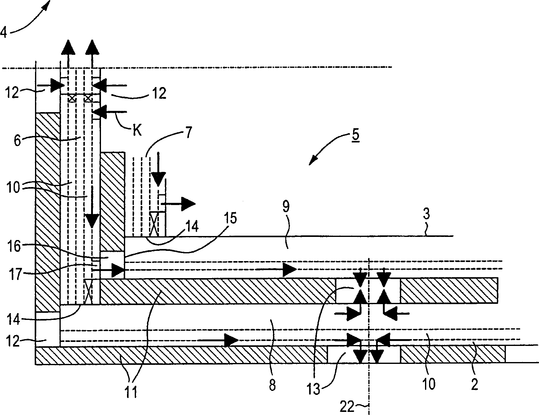
[0022] 1 shows a detail of a generator rotor 1 cooled by a cooling fluid K, with axially extending conductors 2, 3 in the region of the rotor body 4, and comprising longitudinal conductors 6, 7 in the region of the end windings 5, With transverse conductors 8 , 9 extending transversely thereto. Several conductors 2, 3 are stacked radially and form windings G and H, respectively. The windings G, H shown in detail by way of example are the outermost windings of the windings provided on the generator rotor 1, each winding being indicated by A to H from the inside to the outside, the length of each winding increasing from A to G.

[0023] figure 2 Shown in is a detail view of the end winding 5 with longitudinal conductors 6 , 7 and transverse conductors 8 , 9 . In this case, as a starting point in FIG. 1 , the longitudinal conductors 6 , 7 are arranged to the left of the transverse conductors 8 , 9 . Each conductor part 6 to 9 comprises in each case two cooling ducts 10 . Betw...


PUM


Abstract

A number of internally cooled conductors in each case comprise a longitudinal conductor and a transverse conductor connected to it, the longitudinal conductors and the transverse conductors being respectively arranged at least approximately parallel and a small distance apart. Advantageous cooling in terms of fluid mechanics is achieved by a cooling duct of a longitudinal conductor of one conductor being connected to a cooling duct of a transverse conductor of an adjacent conductor.

Description

technical field [0001] The invention relates to an arrangement for internal cooling of electrical conductors, in particular for windings of generator rotors, the electrical conductors comprising in each case a longitudinal conductor and a transverse conductor. In contrast to radial cooling conductors, inner cooling conductors are understood in particular to mean direct inner cooling conductors. Background technique [0002] Electrical conductors designed for high current densities, such as turbine generator windings with a power of about 450 MVA, are usually cooled by internal cooling ducts. At least one cooling duct extends in or directly alongside the conductor cross-section, essentially parallel to the conductor. A cooling fluid, in particular a cooling gas, preferably hydrogen, passes through the or each cooling duct at high velocity, the hydro-mechanical design of the cooling ducts having a direct influence on the flow rate and the cooling effect and the correspondingl...

Claims


Application Information

Patent Timeline
Patent Type & Authority Applications(China)
IPC IPC(8): H02K3/24H02K3/22H02K9/19
CPCH02K3/22
Inventor 于尔根·克拉尔
Owner SIEMENS AG
Learn More