
EEG electrode space positioning method based on up shot measure

A close-range photography and spatial positioning technology, which is applied in 3D image processing, 2D image generation, image data processing, etc., can solve problems such as emission magnetic field distortion, limited measurement accuracy, and high operating environment requirements

Inactive Publication Date: 2003-03-26
TSINGHUA UNIV
View PDF0 Cites 13 Cited by
  • Summary
  • Abstract
  • Description
  • Claims
  • Application Information

AI Technical Summary

Problems solved by technology

[0004] The electromagnetic space position measurement system has the following obvious defects: (1) The operating environment requires high
Because the existence of ferromagnetic materials will cause the distortion of the emitted magnetic field, which will affect the accuracy of the measurement
(2) The measurement accuracy is limited, usually the average position error is about 3-5mm
(3) The system is more complex
(4) When the number of electrodes is relatively large (such as 128 or 256), point-by-point measurement is quite time-consuming

Method used


Image

  • EEG electrode space positioning method based on up shot measure
  • EEG electrode space positioning method based on up shot measure
  • EEG electrode space positioning method based on up shot measure

Examples


Embodiment Construction

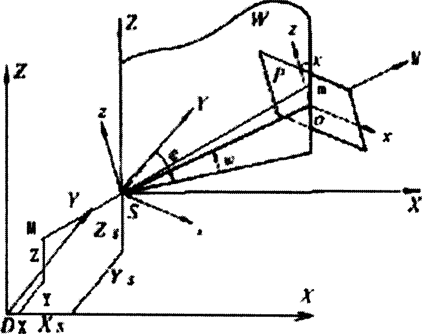
[0021] exist figure 1 , S is the photographic center, and the coordinates are (X s , Y s ,Z s ); M is the control point or the point to be measured, and the actual position of the coordinates is (X, Y, Z); m is the principal point of imaging, and the coordinates are (x, y). In the inverse problem method, it is the image coordinate of the calibration point , in the direct problem method, it is the photo point coordinates; when solving the inverse problem, the image coordinates (x, y), coordinates (X, Y, Z) are known, and when solving the direct problem, the image coordinates (x, y) is known, the coordinates (X, Y, Z) are not known. In the figure, P is the image plane, and W is a plane perpendicular to the x-z plane and forming an angle K with the P plane.

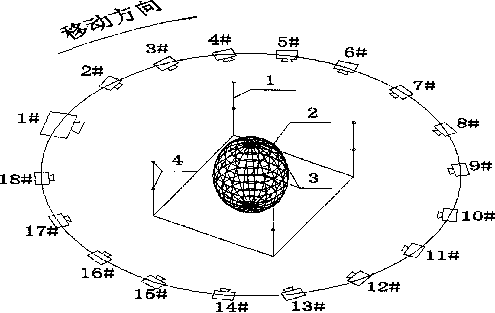
[0022] exist figure 2 Among them, 1 is a calibration object, 2 is a calibration point, 3 is an electrode to be measured, 4 is a point to be measured, 5 is a non-measurement camera, and marks 1-18 are different shooting...


PUM


Abstract

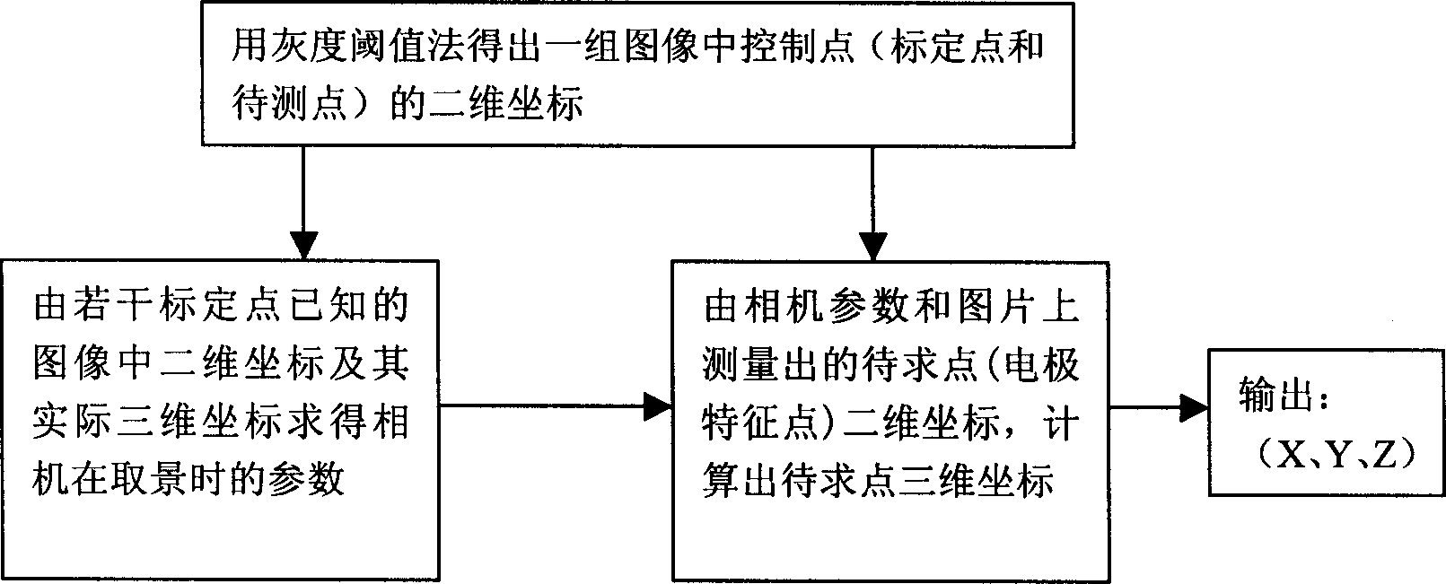
The invention belongs to the technique area of the 3D space orientation, including following steps. The system is composed of the some calibrated objects with the aiming points, the electrode cap having the fixed space positions with calibrated objects, the non-measuring camera, the image processor and the computer. The space coordinate measure of the electrode is completed through the following three steps. The 2D coordinates of the control points (the aiming points and the points to be measured) in the group of image are obtained by using the image recognition method (such as gray scale threshold method). The parameter of the camera at the shooting time can be solved inversely by the collinearity equation in the close-range photogrammetry from the 2D coordinates of the aiming points in the image and its actual 3D coordinates.

Description

technical field [0001] The invention relates to a method for spatial positioning of EEG electrodes based on close-range photogrammetry, which belongs to the technical field of three-dimensional spatial positioning. Background technique [0002] In the process of detecting EEG, the placement of EEG electrodes is a very important link. For different subjects, due to the different shapes of the subjects' skulls and the corresponding internal anatomical positions of the brain, even if the electrodes are placed according to the internationally accepted 10-20 system, the corresponding electrodes of different people at the same nominal position The regions of the intracranial cortex are also different, so that the extracted EEG signals often have large differences. On the other hand, in the test of the same subject, even if there is a small deviation in the placement of the electrodes, the extracted EEG signals often have large differences. Therefore, in order to fully understand...

Claims


Application Information

Patent Timeline
Patent Type & Authority Applications(China)
IPC IPC(8): G03B19/00G06T11/00
Inventor 高小榕高上凯杨福生
Owner TSINGHUA UNIV
Learn More