
Sheet hot sealing device with heat insulating hood

The technology of a heat sealing device and a heat preservation cover is applied in the field of sheet heat sealing devices, and can solve the problems of generating air bubbles, insufficient ability of the roller 31 to maintain the temperature, and long warm-up time.

Inactive Publication Date: 2003-03-19
YUDONG PLASMA TECH
View PDF0 Cites 3 Cited by
  • Summary
  • Abstract
  • Description
  • Claims
  • Application Information

AI Technical Summary

Problems solved by technology

[0003] However, in the above-mentioned common structure, the heating action and the pressing action are completed by two devices and cannot be performed simultaneously, resulting in many restrictions on the combination of plastic film and paper that can be used for plastic sealing, and even poor plastic sealing effects (such as bubbles) ) and other defects
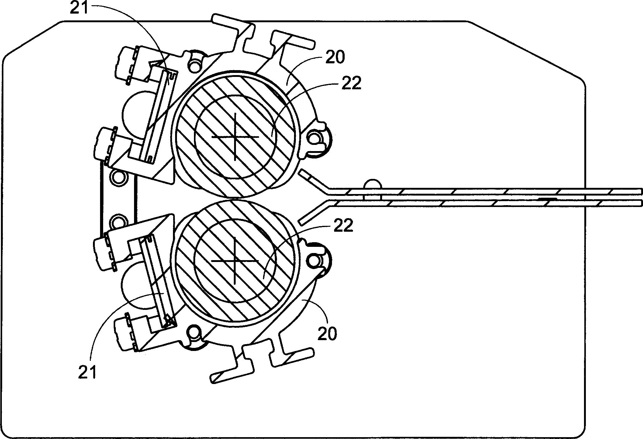
Therefore, in order to improve the above defects, the industry has developed a second common laminator structure as shown in Figure 1(b). This structure, nicknamed "hot shoe", mainly uses an aluminum extruded Type structure 20 to evenly distribute the heat energy generated by the electric heating plate 21, and then make the temperature of the roller 22 rise through the conduction of the air, so that the paper coated with the adhesive film can be heated and heated at the same time when it is fed into the roller 22. The pressing action, in this way, can effectively improve the defects of the above-mentioned plastic sealing machine, but because this common structure heats the roller 22 through air conduction, the roller 22 cannot reach the working temperature quickly and the warm-up time is too long
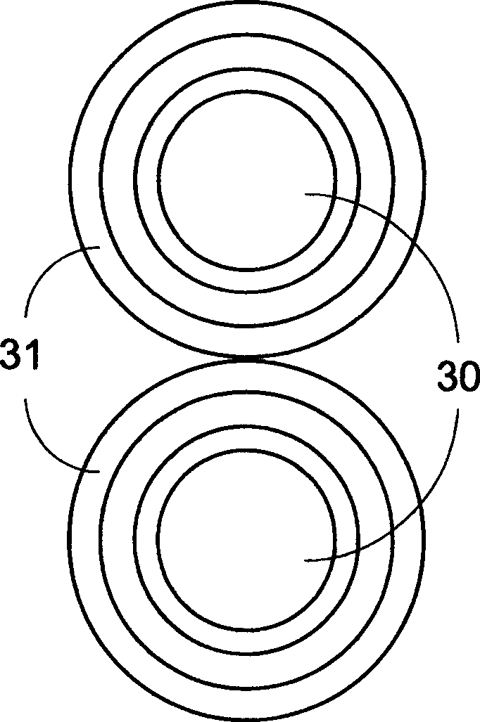
[0004] Therefore, the third common plastic sealing machine structure as shown in Figure 1 (c) has just been developed, and it is mainly that electric heater 30 is arranged among the roller 31, and then can heat this roller 31 from inside to outside and quickly To reach the working temperature, although this structure can reduce the overall volume and improve the heating speed, but also due to the heating method from the inside out, the ability of the roller 31 to maintain the temperature is insufficient, which leads to poor plastic sealing performance, and how to improve the defects of the above structure, For the main purpose of developing the present invention

Method used


Image

  • Sheet hot sealing device with heat insulating hood
  • Sheet hot sealing device with heat insulating hood
  • Sheet hot sealing device with heat insulating hood

Examples


Embodiment Construction

[0019] See figure 2 , is a structural schematic view of a preferred embodiment developed by the present invention to solve common defects, which discloses a sheet heat-sealing device, mainly including a conveying channel 4, which is for several sheets to be heat-sealed (not shown in the figure) , such as two pieces of thermoplastic film and the paper wrapped in between), and the upper and lower sides of the transmission channel 4 are respectively provided with an upper transmission heating and pressing roller 5 and a lower transmission heating and pressing roller 6 (the material of the surface can be rubber completed), wherein the upper transmission heating and pressing roller 5 is composed of a first electrothermal rotating shaft 51 and a first heating and pressing roller 52, and the first heating and pressing roller 52 is covered on the first electrothermal rotating shaft 51 Externally, the electrothermal shaft 51 converts electrical energy into thermal energy and rotates, a...


PUM


Abstract

The sheet hot sealing device includes at least one conveying passage to convey several pieces of sheet to be hot sealed; one first electrothermal shaft on one side the passage to convert electrical energy into heat energy while rotate; one first heating and pressurizing roller, which is around the first electrothermal shaft and is heated by the electrothermal shaft while driving and heating the sheets for combining together; and one first heat insulating hood, which is outside the first heating and pressurizing roller to reflect heat back the roller and maintain constant working temperature.

Description

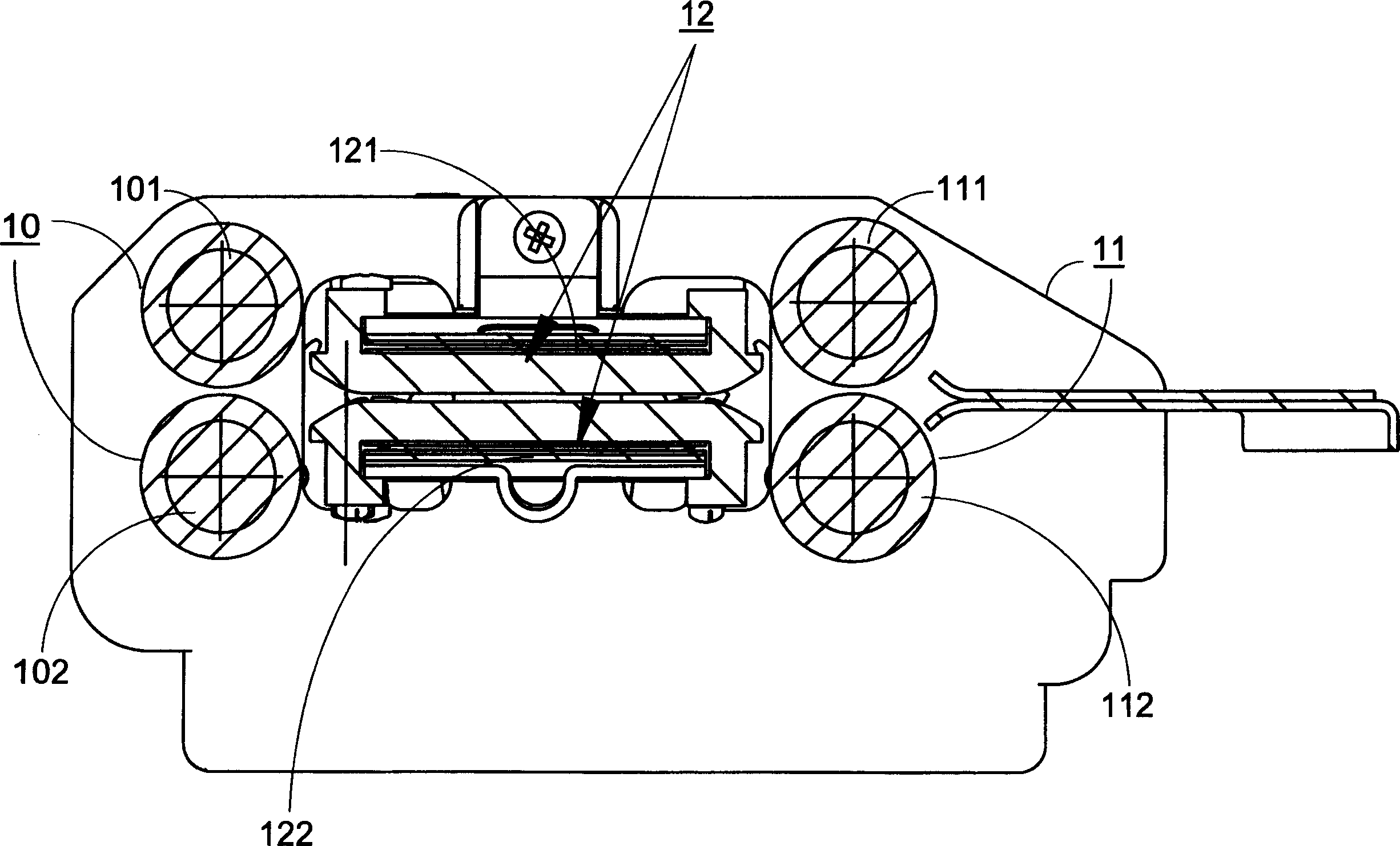
technical field [0001] The invention relates to a sheet heat-sealing device, in particular to a sheet heat-sealing device with a heat preservation cover. Background technique [0002] Please refer to Fig. 1(a), a schematic cross-sectional view of the structure of a common plastic sealing machine at present, which is mainly composed of two front and rear roller sets 10, 11 and a heating device 12, wherein the front roller set 10 and the rear roller set 11 are composed of the above rollers respectively 101, 111 and lower rollers 102, 112, the front roller group 10 feeds the paper (not shown) coated with thermoplastic film up and down into the heating device 12 for heating, and the heating device 12 is mainly composed of upper and lower Composed of two heating structures 121, 122, when the paper covered with adhesive film enters the channel formed between the two heating structures 121, 122, the adhesive film will be heated due to the high temperature caused by the conversion o...

Claims


Application Information

Patent Timeline
Patent Type & Authority Applications(China)
IPC IPC(8): B29C65/02
Inventor 林新富
Owner YUDONG PLASMA TECH
Learn More