Optical head actuator

A technology of actuators and optical heads, applied in the direction of configuration/installation of instruments, heads, recording/reproducing by optical methods, etc., which can solve problems such as reduced operational performance

Inactive Publication Date: 2003-03-12
SAMSUNG ELECTRO MECHANICS CO LTD
View PDF0 Cites 2 Cited by
  • Summary
  • Abstract
  • Description
  • Claims
  • Application Information

AI Technical Summary

Problems solved by technology

However, this conventional magnetically driven optical head actuator has a problem in that its operability is degraded because its magnetic circuit does not form a closed loop but has a gap.

Method used


Image

  • Optical head actuator
  • Optical head actuator
  • Optical head actuator

Examples


Embodiment Construction

[0021] Referring now to the drawings, in the drawings, the same reference numerals denote the same components.

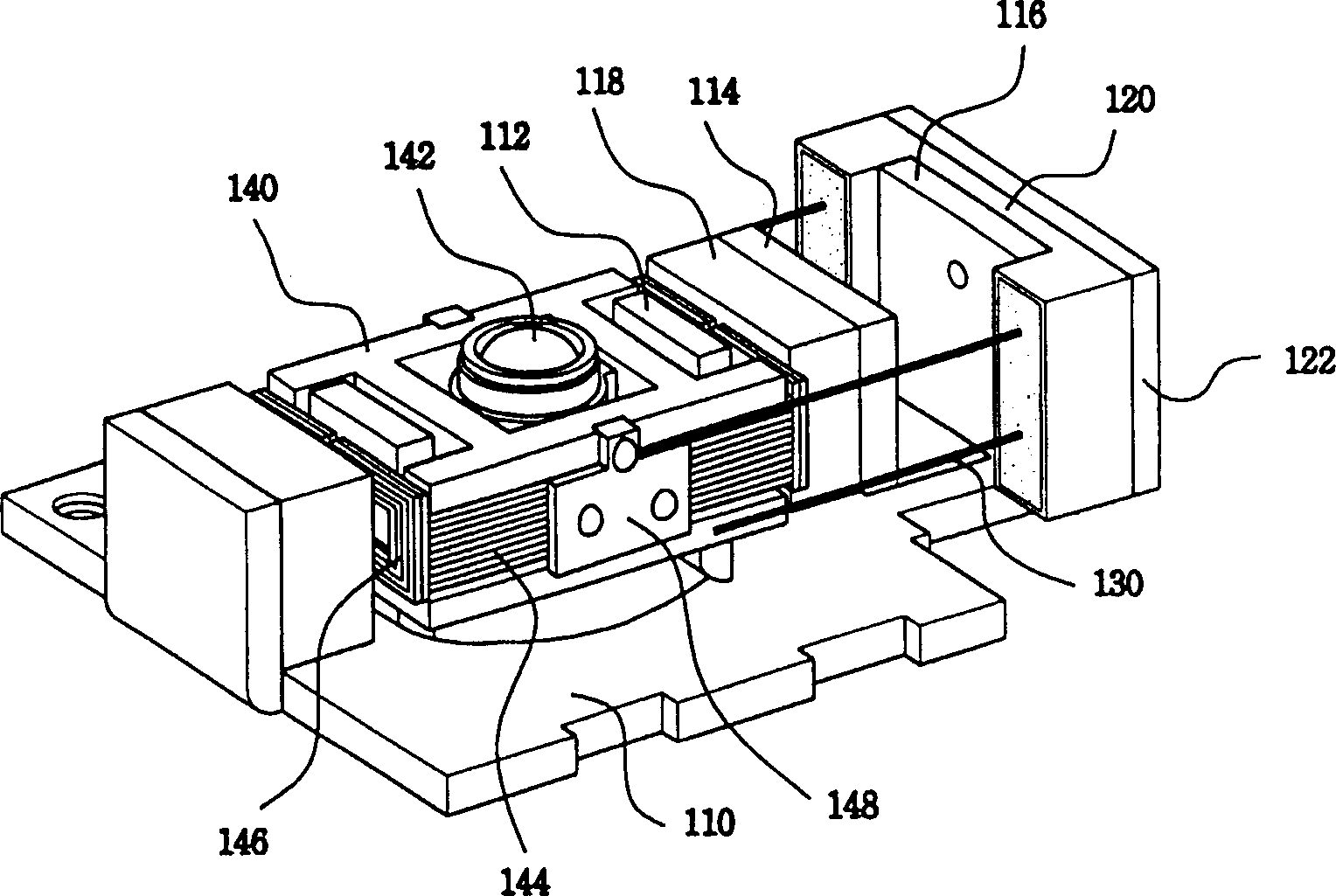
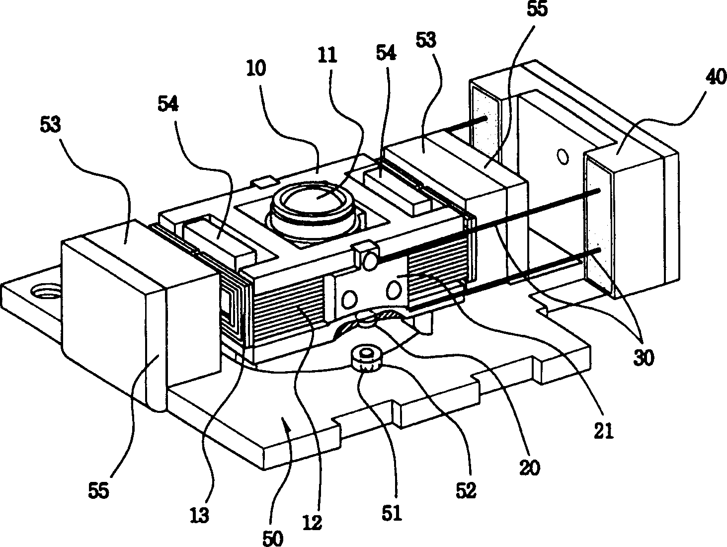
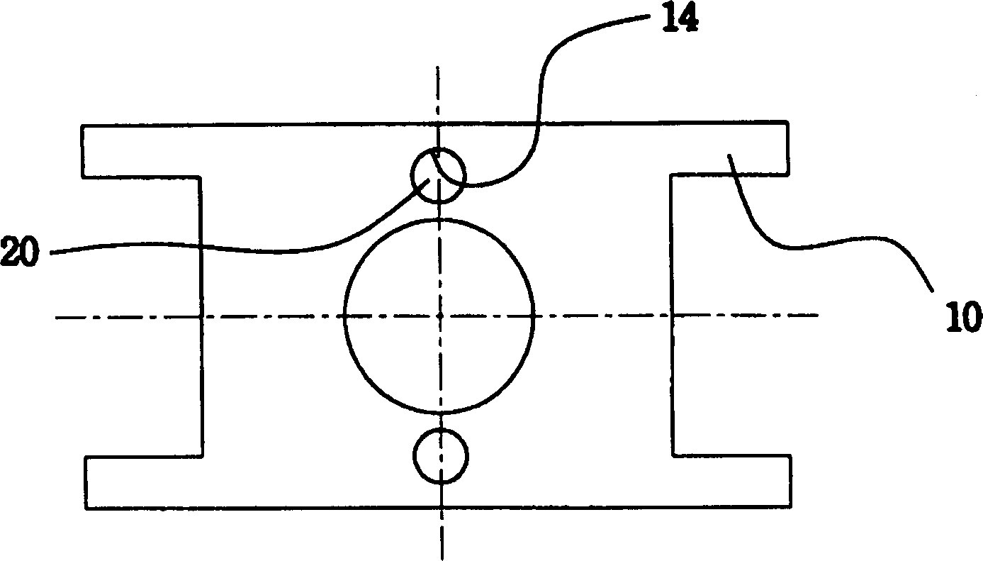
[0022] figure 2 A perspective view of the optical head actuator according to the first embodiment of the present invention is shown. image 3 Shown included in figure 2 The bottom view of the transfer device in the optical head actuator is shown, in which two inclined magnets are provided at completely opposite positions on the lower surface of the transfer device along the transverse central axis of the transfer device.

[0023] As shown in the figure, the optical head actuator according to the present invention includes: a transfer device 10 having an objective lens 11 at the center of its upper part for focusing light; and a drive coil unit wound on its outer surface.

[0024] The driving coil unit includes a focus coil 12 and two tracking coils 13. The focus coil 12 is wound on the outer surface of the transfer device 10, and at the same time, two coils PCB21 are...


PUM


Abstract

An optical pick-up actuator for optical pick-up devices is disclosed. In the actuator of this invention, the blade positioned to float above a yoke plate has one focusing coil, two tracking coils and two tilting magnets. The yoke plate has two side yokes holding two tilting coils at positions vertically aligned with the two tilting magnets. The tilting magnets are formed on the lower surface of the blade at positions, which are symmetrical around the perpendicular optical path of an object lens of the blade or around the tilting axis of the blade. The tilting magnets of the blade and the tilting coils of the yoke plate are operated under the control of a solenoid. When a current flows in the tilting coils, the tilting magnets generate electromagnetic fields to tilt the blade at a desired angle relative to the perpendicular optical path of the object lens. The pick-up actuator thus stably performs a blade tilting operation in addition to performing conventional focusing and tracking operation, and so the actuator allows the object lens to precisely focus a laser beam on a disc, particularly, a high density optical DVD, and allows an optical pick-up device to precisely read or write information from or onto the disc even when the disc is inclinedly positioned in the deck of a disc player.

Description

Technical field [0001] The present invention generally relates to an optical head actuator, which is used to focus the objective lens of an optical pickup device with respect to the optical disc and track the optical disc when reading information from or writing information to the optical disc. More specifically, the present invention It relates to an optical head actuator with a blade, which is floatingly mounted above a yoke plate and can be tilted with respect to the yoke plate, so that even when the optical disc is placed obliquely to the disc of the optical disc player When in the deck, the optical pickup device can also accurately read information from or write information to a high-density optical disc. Background technique [0002] As those skilled in the art know, the optical head actuator is the actuating part of the optical pickup device. It moves the objective lens of the optical pickup device in the radial direction to find the required track on the optical disc, and...

Claims


Application Information

Patent Timeline
Patent Type & Authority Applications(China)
IPC IPC(8): G11B7/085G11B7/09G11B7/095
CPCG11B7/0956G11B7/093G11B7/095G11B7/0935G11B7/0932G11B7/085
Inventor 郑镐燮
Owner SAMSUNG ELECTRO MECHANICS CO LTD
Why Eureka
Try Eureka