Washing machine
A washing machine and washing water technology, applied in the field of washing machines, can solve the problems of noise, the washing machine cannot correspond to the spraying method of washing water, and the cost is increased.
- Summary
- Abstract
- Description
- Claims
- Application Information
AI Technical Summary
Problems solved by technology
Method used
Image
Examples
Embodiment 1
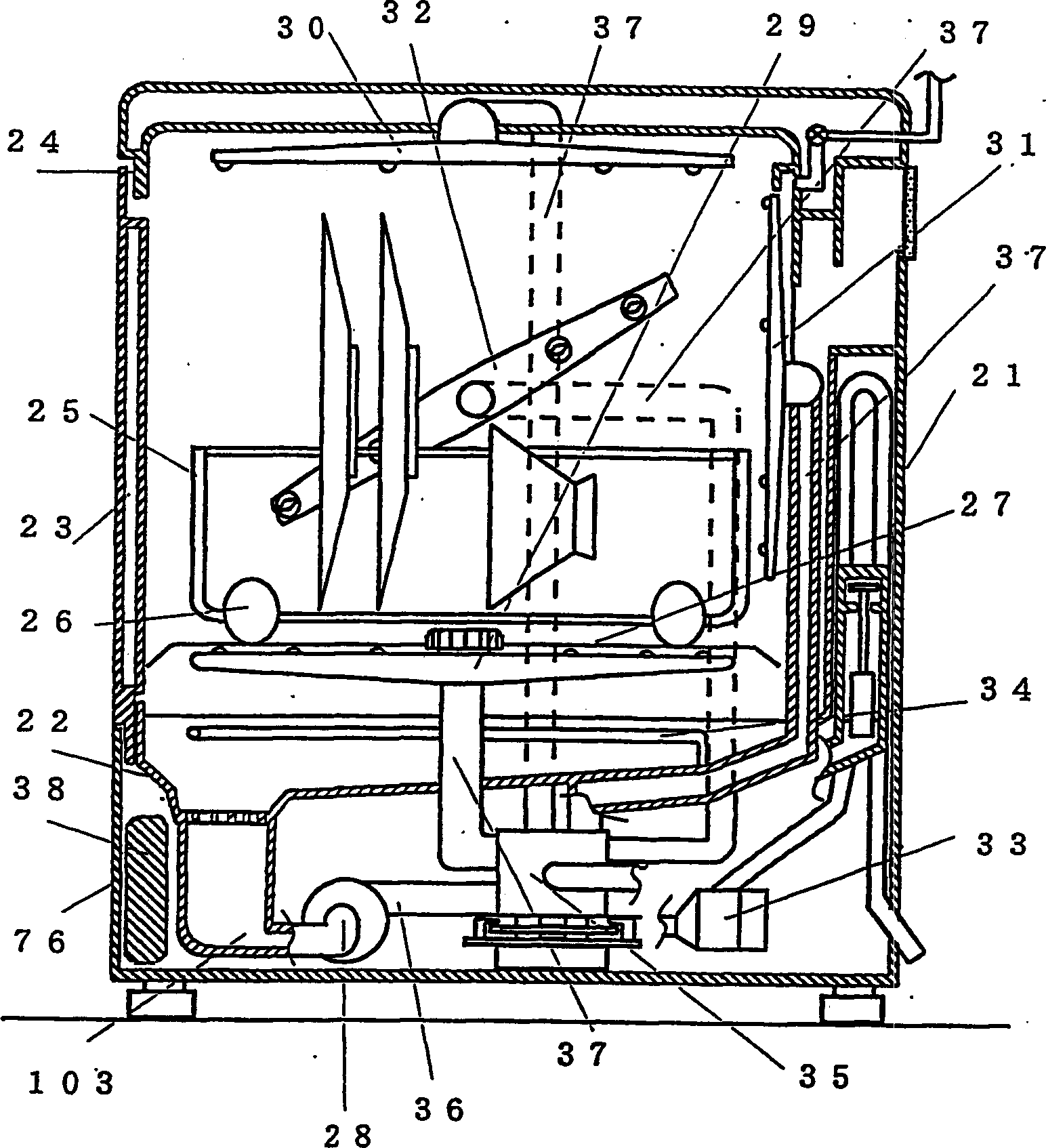
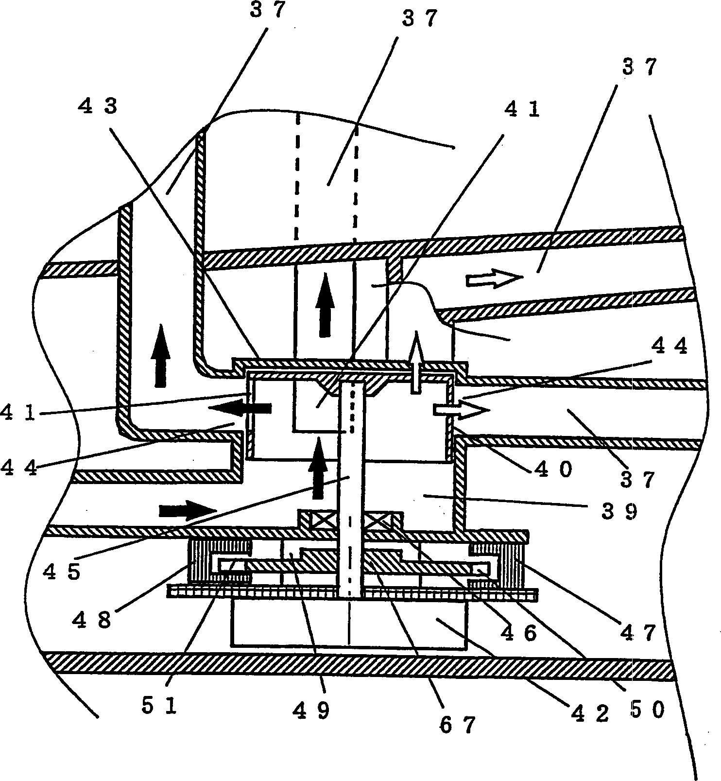
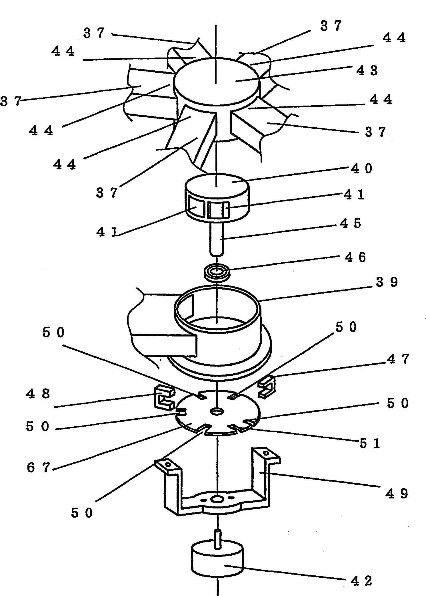
[0108] figure 1 It is a cross-sectional view of the dishwasher according to Embodiment 1 of the present invention. figure 2 yes means figure 1 Partial cross-sectional view of the composition of the water diversion device of the dishwasher and the flow direction of the washing water. image 3 It is an exploded perspective view showing the water separation mechanism of the dishwasher. Figure 4 It is a partial sectional view showing the drive mechanism of another water diversion device of the dishwasher. Figure 5 It is a perspective view which shows the structure of another washing apparatus of this dishwasher. Image 6 It is a perspective view which shows the structure of another washing apparatus of this dishwasher. Figure 7 It is a perspective view which shows the structure of another washing apparatus of this dishwasher. Figure 8 It is a perspective view which shows the structure of another washing apparatus of this dishwasher. Figure 9 It is a perspective view ...
Embodiment 2
[0129] Figure 11 It is a cross-sectional view of a dishwasher according to Embodiment 2 of the present invention.
[0130] Compared with the structure of Example 1, the cleaning machine of this Example has the following different structures. That is, the washing pump 28 is arranged vertically. The water supply port of the cleaning pump is arranged at the lowermost part of the cleaning pump. The washer pump discharge port 36 is provided on the upper portion of the washer pump water supply port 81, and protrudes substantially horizontally. A water separation discharge port 44 is provided at a position higher than the washer pump discharge port 36 . A micro switch is provided on the fixed position of the rotating water diversion part, the rotation angle detection sensor 47 for detecting the rotation angle during rotation, and the positioning positioning sensor 48 for positioning, and the rotation detection disk 67 formed with unevenness on the surface is arranged. . As a de...
Embodiment 3
[0136] Fig. 13 is a partial sectional view showing the structure of the water diverting device and the flow of washing water according to Embodiment 3 of the present invention. Figure 14 It is an exploded perspective view showing the water separation structure of the dishwasher.
[0137] Compared with the cleaning machine of Example 1, the washing machine of the present Example 3 has the following different configurations. That is, the plurality of discharge ports 41 are provided at positions shifted up and down by an arbitrary distance from each other in the axial direction of the rotary water diversion part 40 . The rotation trajectories of the discharge ports 41 are different from each other. Washing water discharge passages 37 having water separation discharge ports 44 are also provided on different planes.
[0138] In addition, regarding the offset of the rotation trajectories of the discharge ports 41, the rotation trajectories of the respective discharge ports 41 may...
PUM
 Abstract
Description
Claims
Application Information
 - Generate Ideas
- Intellectual Property
- Life Sciences
- Materials
- Tech Scout
- Unparalleled Data Quality
- Higher Quality Content
- 60% Fewer Hallucinations
Browse by: Latest US Patents, China's latest patents, Technical Efficacy Thesaurus, Application Domain, Technology Topic, Popular Technical Reports.
© 2025 PatSnap. All rights reserved.Legal|Privacy policy|Modern Slavery Act Transparency Statement|Sitemap|About US| Contact US: help@patsnap.com


