Image forming unit and displaying unit

An image and image density technology, which is applied to the electrical recording process using charge graphics, equipment and instruments using the electrical recording process using charge graphics, etc., and can solve the problems of increased user waiting time, increased toner, and wasted toner.

Inactive Publication Date: 2003-02-26
CANON KK
View PDF0 Cites 7 Cited by
  • Summary
  • Abstract
  • Description
  • Claims
  • Application Information

AI Technical Summary

Problems solved by technology

However, on the contrary, there is such a disadvantage for the user that since no image is formed during the density control, the time in the density control is not only useless time, but also the toner is wasted in vain by forming interleaved images. , and, unnecessarily increases waste toner
In this case, as described above, an increase in user's waiting time, consumption of toner, and increase in waste toner will be incurred.

Method used


Image

  • Image forming unit and displaying unit
  • Image forming unit and displaying unit
  • Image forming unit and displaying unit

Examples


Embodiment Construction

[0018] Hereinafter, embodiments of the present invention will be described with reference to the drawings.

[0019]

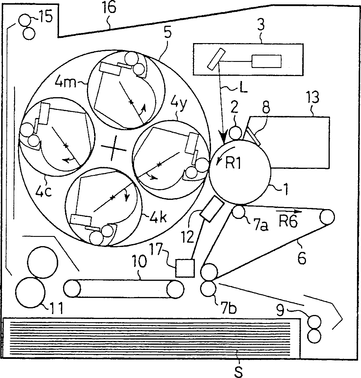
[0020] figure 1 An example of an image forming apparatus according to the present invention is shown. The image forming apparatus shown in this figure is an electrophotographic 4-color full-color laser printer, and this figure is a longitudinal sectional view schematically showing its schematic configuration.

[0021] The image forming apparatus shown in the figure includes a drum-shaped electrophotographic photoreceptor (hereinafter referred to as a “photosensitive drum”) as an image bearing member.

[0022] The photosensitive drum 1 is driven by a driving device in the direction of an arrow R1 in the figure, and is charged with a prescribed polarity and potential by a charging roller (charging device) 2 . Then, a laser beam L with a yellow image pattern is irradiated onto the surface of the photosensitive drum 1 from an exposure device (laser scanner) 3 ,...


PUM


Abstract

Any reduction in the dignity of image, any increase in the waiting time, any increase in toner consumption and waste toner, etc. are prevented. A memory is provided in a developing device detachably mountable to the main body of an image forming apparatus, and a main body memory is provided in the main body. The last optimum bias stored in the memory in the developing device and the newest development bias are compared with each other (S14), and on the basis of the difference ”Di therebetween, the interval at which density detection is effected is changed. When ”Di‰¥A, the interval is shortened (S18), and when A>”Di‰¥B, the interval is not changed, and when B>”Di, the interval is lengthened. Thereby, necessary minimum density control is effected to thereby prevent any reduction in the dignity of image and any increase in the waiting time.

Description

technical field [0001] The present invention relates to image forming apparatuses such as printers and copiers. Background technique [0002] In image forming apparatuses such as printers and copiers, a density control device that automatically adjusts the density of an output image (for example, a toner image) to an appropriate density is generally provided. In particular, in an image forming apparatus that outputs four-color full-color toner images, more accurate density control for each color toner image of yellow, magenta, cyan, and black is required in order to obtain a desired color balance. [0003] Density detection is performed by a method in which a toner image (hereinafter referred to as a patch image as appropriate) of a specific halftone pattern according to area gradation is formed on a photosensitive drum (image bearing member) and used A reflected light amount sensor composed of a light emitting element and a light receiving element measures the amount of re...

Claims


Application Information

Patent Timeline
Patent Type & Authority Applications(China)
IPC IPC(8): G03G15/00G03G15/06G03G15/08G03G21/14
CPCG03G15/5041G03G2215/0177G03G2215/00042G03G15/0896G03G21/1889G03G15/00
Inventor 星加令久
Owner CANON KK
Why Eureka
Try Eureka