Dehairing device

A hair removal device and cylinder technology, which can be used in hair or scalp washing devices, clothing, hairdressing equipment, etc., can solve the problems of difficulty in pulling out body hair, inconvenient use, stimulation, etc., and achieve the effect of improving hair removal efficiency and convenient use

Inactive Publication Date: 2003-01-01
MATSUSHITA ELECTRIC WORKS LTD
View PDF2 Cites 7 Cited by
  • Summary
  • Abstract
  • Description
  • Claims
  • Application Information

AI Technical Summary

Problems solved by technology

[0004] But, in the above-mentioned hole of prior art example, or the hole that is extended along the axial direction of the depilatory roller as rotating member or be wavy, so when making the depilatory device move close to the skin for depilation, the side walls of the hole are opposite to each other. There is a certain angle in the direction of travel, the risk of being blocked by the skin is very high, and the resistance to movement on the surface of the skin increases, which is very inconvenient to use
In addition, since the force applied to the skin becomes larger, there is a problem of damaging the skin
[0005] In addition, since the skin protection member is located between the skin and the epilation roller, the thickness of the skin protection member is also a problem
If it is thickened to maintain its strength, short body hair cannot be gripped and cannot be pulled out, and if it is thin, it is difficult to maintain its strength
[0006] In addition, in the above-mentioned prior art examples, the paired depilatory rollers are rotated in opposite directions to clamp body hair, but since the clamped body hair is away from the skin surface, shorter body hair cannot be removed.
[0007] In addition, since the body hair is held over the entire length of the hair removal roller in the length direction, many body hairs are pulled out at the same time, which is very irritating and causes great pain
In addition, since a pair of rollers are required, the part that touches the skin becomes larger, and it is difficult to pluck body hair from relatively narrow parts such as underarms.

Method used


Image

  • Dehairing device
  • Dehairing device
  • Dehairing device

Examples


Embodiment Construction

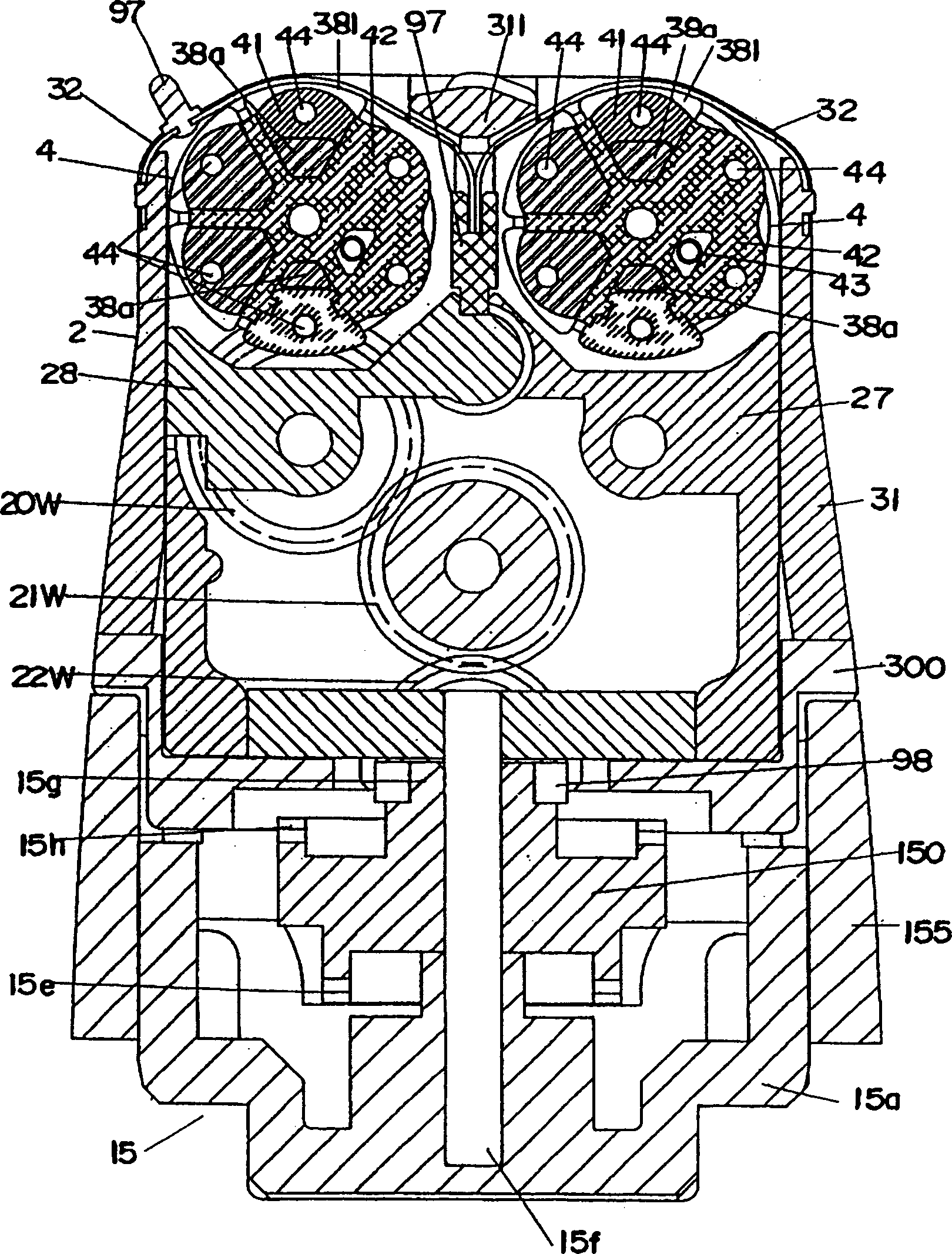
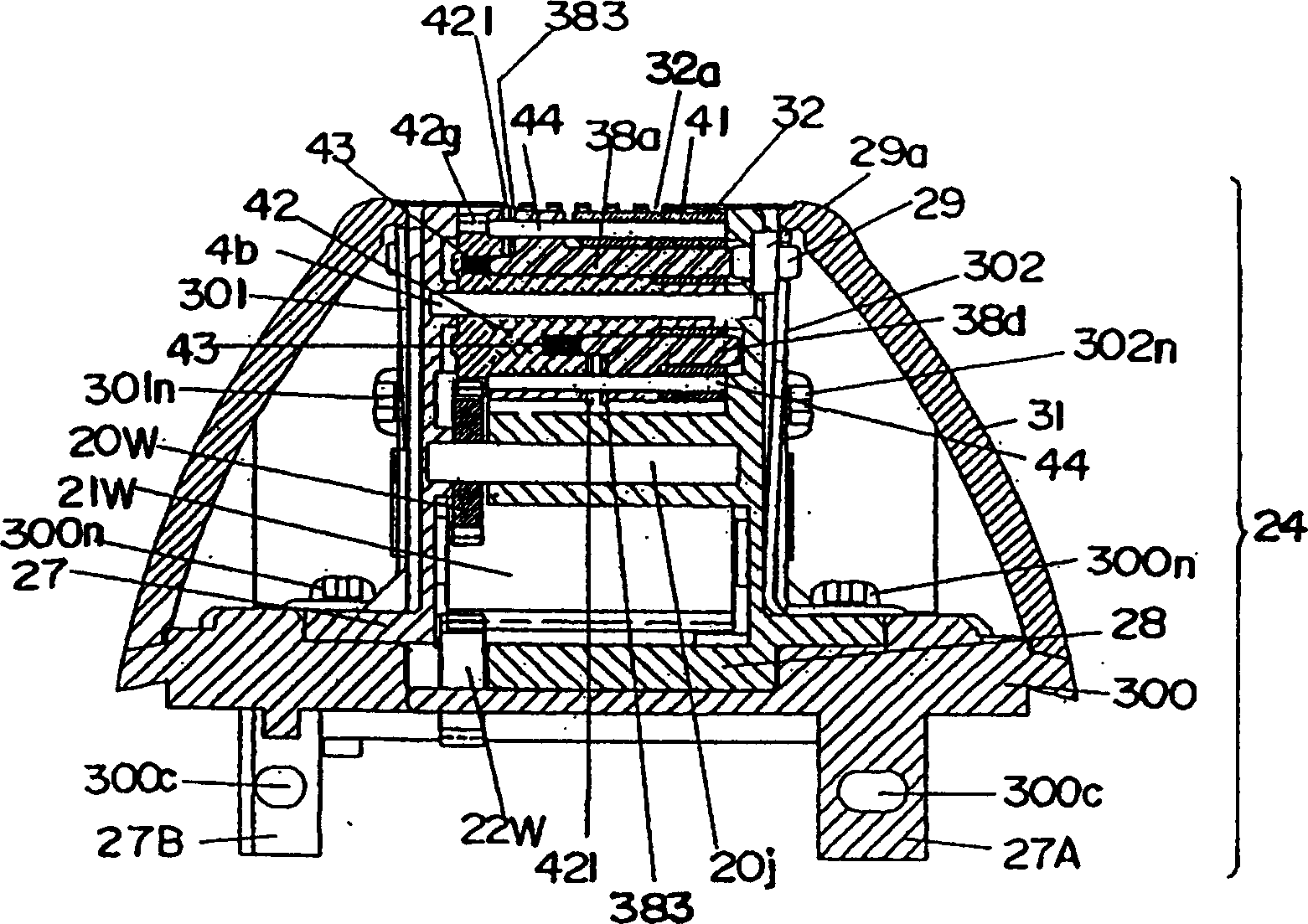
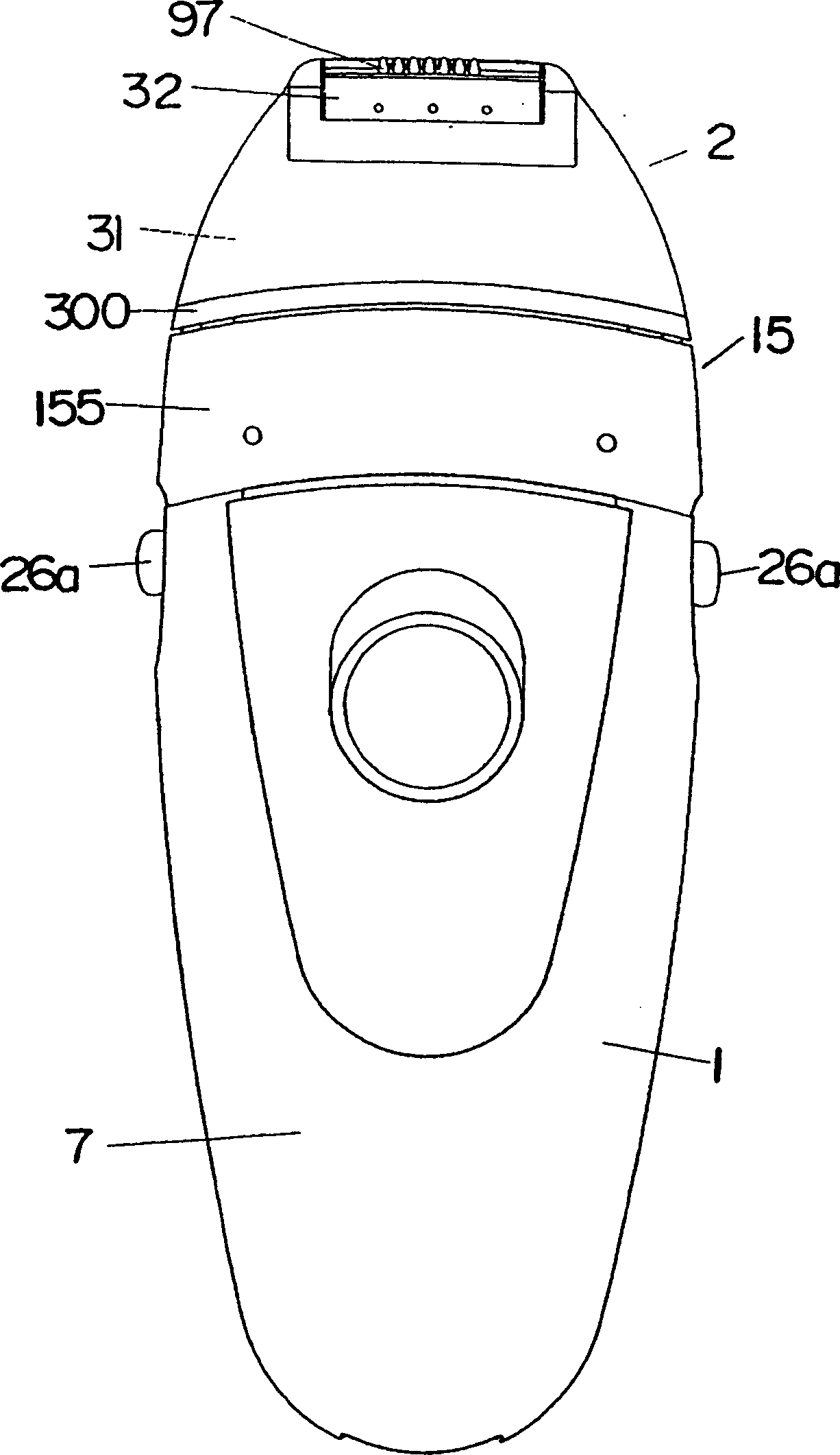
[0068] Below, an example of the embodiment shown in the accompanying drawings will be described, wherein, the depilatory device of the example shown in the drawings, such as Figure 3 ~ Figure 6 As shown, on the main body casing 1 of a size that can be grasped by hand and a motor 3 built in as a driving source, a hair removal head 2 equipped with a rotating cylinder 4 is provided. A depilatory mechanism composed of a plurality of claws 411, 383 of body hair, along with the rotation of the rotating cylinder around the axis, the depilatory mechanism grips the body hair and pulls it out.

[0069] Such as image 3 and Figure 8 As shown, the main body shell 1 equipped with the switch S on the front is composed of split shells 7, 7 cut into front and rear halves that are joined together by small screws 7n, and its upper end opening is held by the motor 3 and the drive transmission mechanism and accommodates The upper part of the base 8 in the main body casing 1 is closed, and the...


PUM


Abstract

The present invention provides a depilating device which includes one pair of depilating claws that are opened and closed by a cylindraceous rotating cylinder driven by rotation to pinch and pull out the hair insert-held by the claw due to a rotation of the rotating cylinder. A plate covers the outer surface of the rotating cylinder, and has a slit extended along a direction parallel to the rotating direction of the rotating cylinder. The rotating cylinder and the depilating claws are prevented from being in contact with the skin by the plate, and the hair is introduced from the slit formed at the plate and pinched and pulled by the claws. Thereby short hairs can be depilated without damaging the skin.

Description

technical field [0001] The present invention relates to a depilatory device for plucking body hair for cosmetic purposes. Background technique [0002] From the patent Nos., JP-2-29208 and JP-2-215406, it is known that a clamping member for body hair is arranged on a rotationally driven component, and a depilatory device that pulls out the clamped body hair by means of rotary motion . [0003] In this depilatory device, since the rotating member and the body hair clamping member may injure the skin when they directly contact the skin, in the above-mentioned prior art example, a skin protection member covering the rotating member equipped with the body hair clamping member is provided. At the same time, the body hair is guided to the side of the rotating member through the hole provided on the skin protection member. [0004] But, in the above-mentioned hole of prior art example, or the hole that is extended along the axial direction of the depilatory roller as rotating mem...

Claims


Application Information

Patent Timeline
Patent Type & Authority Applications(China)
IPC IPC(8): A45D26/00
CPCA45D26/0033A45D26/00
Inventor 井上朋之末吉秀一
Owner MATSUSHITA ELECTRIC WORKS LTD
Why Eureka
Try Eureka