Eureka AIR delivers breakthrough ideas for toughest innovation challenges, trusted by R&D personnel around the world.

Valve with lock

A valve and lock technology, which is applied to valve details, valve devices, cocks including cut-off devices, etc., can solve the problems of increasing the amount of valves with locks, high product costs, broken keys, etc., and achieves reasonable structure, low cost and practicality. strong effect

Inactive Publication Date: 2002-12-11
刘金凤
View PDF3 Cites 6 Cited by
  • Summary
  • Abstract
  • Description
  • Claims
  • Application Information

AI Technical Summary

Problems solved by technology

[0004] For the above-mentioned first type of valve with lock, they add a lock body structure on the basis of traditional valves, and retain the handle of the traditional valve. Therefore, although the operation is more convenient, the structure of the product is more complicated and the product cost is higher. High, especially in the case of a sharp increase in the current use of lock valves, it is difficult to be widely used
For the above-mentioned second type of valve with lock, if the method of directly replacing the handle with a key is adopted, practice shows that it is very laborious to operate the valve, and the key is often broken
If a special opening tool is used, that is to say, a key and a special tool are required to operate a valve, which makes it inconvenient to carry and operate.

Method used


Image

  • Valve with lock
  • Valve with lock
  • Valve with lock

Examples


Embodiment Construction

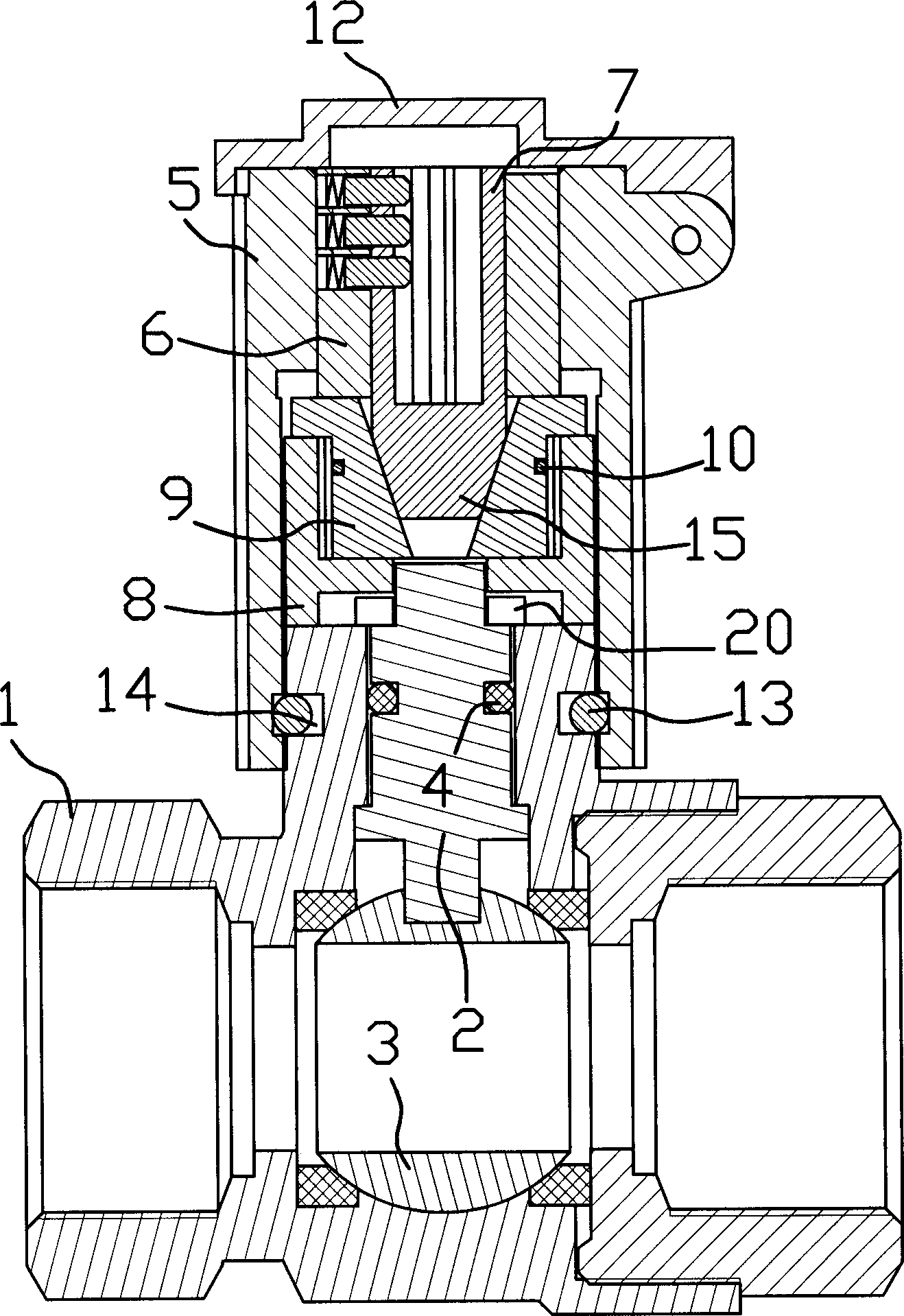
[0028] Such as figure 1 As shown, in this embodiment, the valve with lock is a ball valve, which includes parts such as valve body 1, valve core 3, valve stem 2, lock housing 5, lock body 6 and lock core 7. The valve core 3 is spherical, the inner end of the valve stem 2 is connected with the valve core 3 , and the outer end of the valve stem 2 protrudes from the valve body 1 and is located in the lock housing 5 . An ○-shaped rubber sealing ring 4 for sealing is also provided between the valve stem 2 and the valve body 1 .

[0029] Such as figure 1 As shown, the lock housing 5 is cylindrical and sleeved on the valve body 1 . An annular groove 14 is provided on the inner side of the lock housing 5 and the outer side of the valve body 1 at the joint between the lock housing 5 and the valve body 1 , and a snap ring 13 is stuck in the two annular grooves 14 . The lock case 5 is axially fixed on the valve body 1 by means of the snap spring 13 . That is to say, the lock housing ...


PUM


Abstract

The valve with lock includes valve body, valve core inside the valve body, valve rod with inner end connected to the valve core and outer end extending beyond the valve body and into a cylindrical locking casing in the upper part of the valve body. There is a clutch mechanism between the lock body in the locking casing and the valve rod for linkage or separation. The clutch mechanism is controlled by the lock body and when the clutch mechanism makes the lock body and the valve rod in linkage state, rotating the locking casing only can rotate the valve rod and valve core simultaneously to control the valve. The valve has reasonable structure and is practical.

Description

technical field [0001] The invention belongs to the technical field of valves, in particular to a valve with a locking device. Background technique [0002] After the valve is installed on the pipeline, people can usually open or close it at will. However, for some functional departments or companies that supply water, heating, and gas, they need to rely on valves to control the opening and closing of pipelines while providing tap water, heating, or gas to consumers through pipelines. Users who pay on time will stop supplying. Therefore, it is necessary to install a locking device on the valve to prevent others from opening it illegally. In this way, there are many valves with locking devices. [0003] From the structure of the product, the existing valves with locks can be roughly divided into two categories: one is to use the lock body to lock the valve stem in the valve to control the opening and closing of the valve. For example, the "valve with lo...

Claims


Application Information

Patent Timeline
Patent Type & Authority Applications(China)
IPC IPC(8): F16K5/00F16K35/00
Inventor 林淑敏
Owner 刘金凤
Why Eureka
Eureka Blog
Learn More