


Quick Research
Generate reliable direction feasibility study reports for your R&D in just a few steps.

Technical Q&A
Discover and master advanced knowledge NOW. Basics, ideas, possibilities, all at once.

Find Solutions
As an expert in R&D theories, this can generate solutions to your technical problems instantly.

Evaluate Feasibility
Analyze your overall solution with one click, know your potential R&D risks in advance.

Monitor Landscape
Get weekly tech updates, stay abreast of the latest tech innovations and key insights.
Stirling engines
A technology of Stirling engine and power cylinder, which is applied in the direction of Stirling engine, engine components, machine/engine, etc., can solve the problems of large volume and reduced freedom of machine layout, so as to improve theoretical efficiency and increase the scope of application. , the effect of increasing degrees of freedom
- Summary
- Abstract
- Description
- Claims
- Application Information
AI Technical Summary
Problems solved by technology
Method used
Image

Examples
Embodiment Construction
[0037] Embodiments of the present invention are described below with reference to the accompanying drawings.
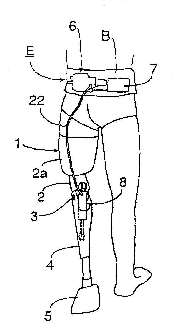
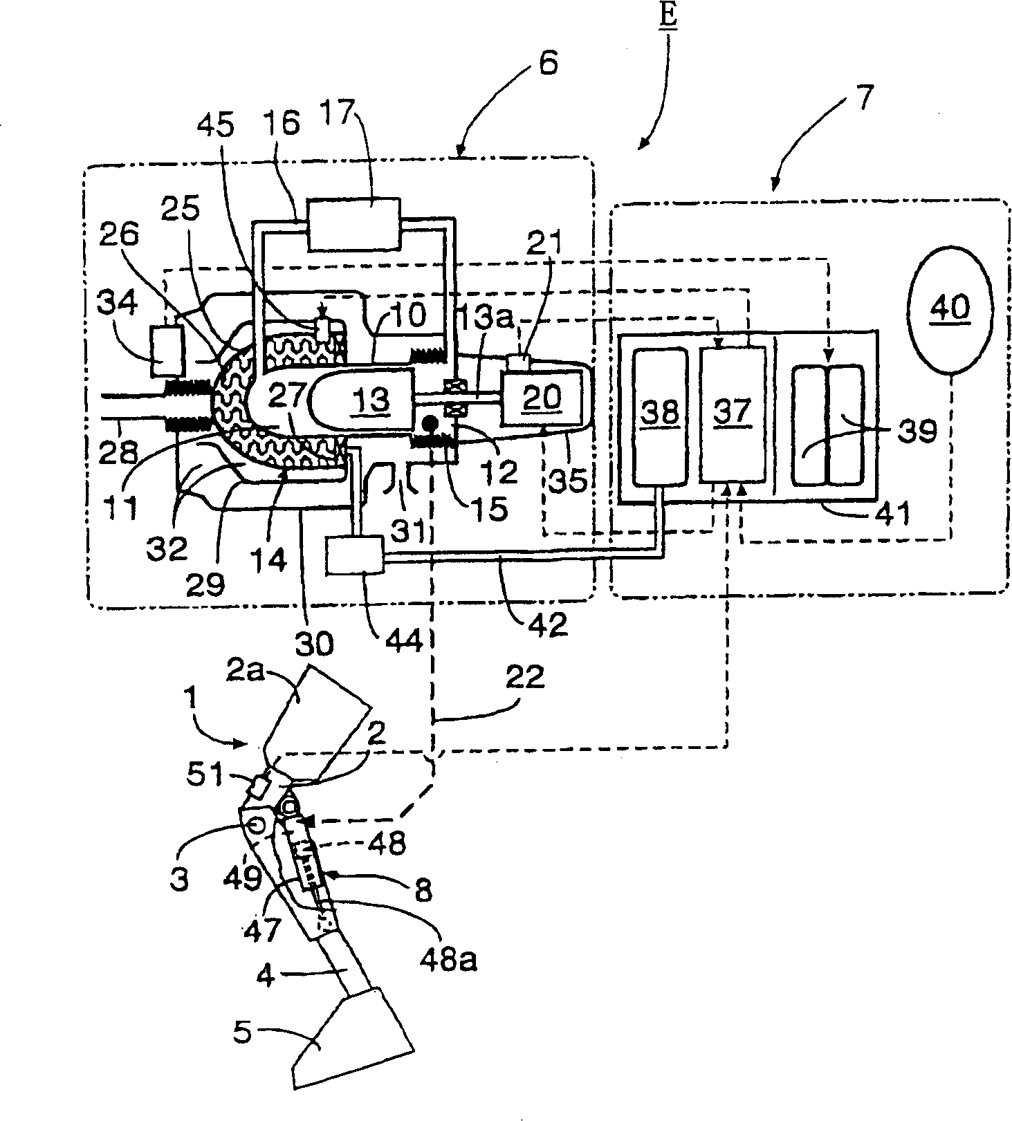
[0038] according to figure 1 and figure 2 A first embodiment of the invention is shown, figure 1 and figure 2 The Stirling engine E of the present invention is illustrated. Usually used to drive prosthetic legs 1 . The prosthetic leg 1 comprises a prosthesis 2 integral with a socket 2a; the socket 2a is for insertion of the residual leg by the patient. The artificial tibia 4 is flexibly / extendably connected to the lower end of the artificial thigh 2 through the artificial joint, and the foot 5 is connected to the lower end of the artificial tibia 4 .
[0039] The Stirling engine E comprises a purge unit 6 and a control unit 7 . These two parts are mounted on the belt B, which is worn on the waist of the patient. The power cylinder 8 is installed on the prosthetic leg 1 and is located between the prosthetic thigh 2 and the prosthetic shin 4 . The pressure lin...
PUM
 Abstract
Description
Claims
Application Information
 - R&D Engineer
- R&D Manager
- IP Professional
- Industry Leading Data Capabilities
- Powerful AI technology
- Patent DNA Extraction
Browse by: Latest US Patents, China's latest patents, Technical Efficacy Thesaurus, Application Domain, Technology Topic, Popular Technical Reports.
© 2024 PatSnap. All rights reserved.Legal|Privacy policy|Modern Slavery Act Transparency Statement|Sitemap|About US| Contact US: help@patsnap.com