
Image processing method for image transmission system and its optical fibre endoscope

A transmission system and image processing technology, applied in image data processing, endoscopes, components of TV systems, etc., can solve the problem that the single fiber filaments cannot be arranged neatly and closely with the same coordination, which has a large impact and increases production costs and products. Disqualification rate, etc.

Inactive Publication Date: 2002-10-30
TSINGHUA UNIV
View PDF0 Cites 46 Cited by
  • Summary
  • Abstract
  • Description
  • Claims
  • Application Information

AI Technical Summary

Problems solved by technology

Therefore, the production process of the lamination method has great limitations. First, the judgment of the accuracy of Moiré fringes in the operation can only be qualitative but not quantitative, and the influence of human factors is large; secondly, the diameter of the single filament should not be less than 12. production is very difficult
[0013] For example, the Third Research Institute of Nanjing Glass Fiber Research and Design Institute adopts the lamination process to manufacture the image beam. Due to the limitations of the process itself, the manufacturing error of the production equipment, and the subjective influence of human factors, it is impossible to completely guarantee the two-dimensionality of the image beam in a strict sense. The monofilaments at the end are arranged neatly and closely and are coordinatingly arranged, so the observed image actually has grid and some pixel misalignment.
The lamination method to manufacture the optical fiber image transmission bundle is also due to the influence of broken wires and dark wires, and the yield is low, thus increasing the production cost and product failure rate

Method used

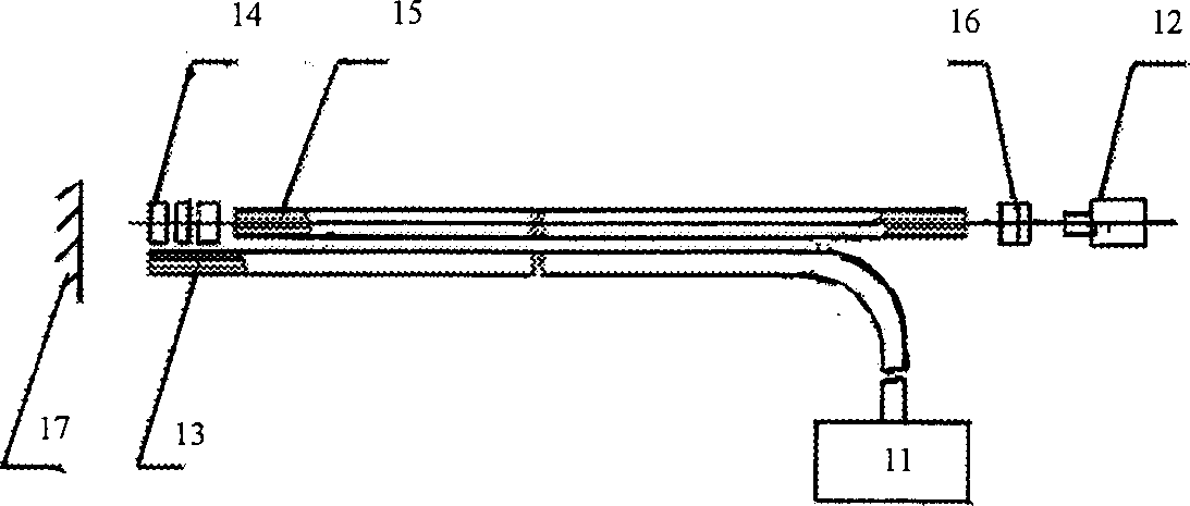
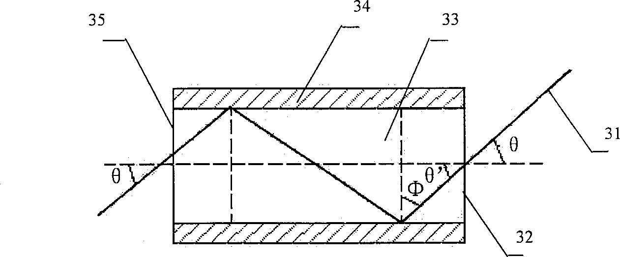

Image

  • Image processing method for image transmission system and its optical fibre endoscope
  • Image processing method for image transmission system and its optical fibre endoscope
  • Image processing method for image transmission system and its optical fibre endoscope

Examples


Embodiment Construction

[0044] The image processing method used in the image transmission system proposed by the present invention and the fiber optic endoscope designed by this method are described in detail below in conjunction with the drawings and embodiments.

[0045] The basic structure of the optical fiber endoscope device designed by the image processing method of the present invention is as follows: Figure 5 Shown, comprise light source 51, transmission light beam 52, objective lens 53, image transmission beam 54, eyepiece 55, CCD camera 56, image acquisition processing unit 57 (ie the computer that image acquisition card is installed), monitor 58. On the basis of the structure of the existing endoscope device, the present invention uses non-isocoordinated image beams 54 to replace the co-ordinated image beams. Therefore, the acquired image information of the measured object 59 is messy , the image cannot be directly observed through the eyepiece 55, and the real image cannot be directly di...


PUM


Abstract

An image processing method for image transmission system includes two parts: scaling and real measuring, which can restore and restructure real image by processing the disorder image information of the object to be measured. An optical fibre endoscope designed by said method is composed of light delivering unit and image transmission unit. Said light delivering unit consists of light source, coupling lens and optical fibres. Said image transmission unit consists of optical fibres, eyepiece, CCD camera, image acquiring and processing unit and monitor. Its advantages are simple structure, simplified process for preparing optical fibres, and low cost.

Description

technical field [0001] The invention belongs to the field of image processing and endoscope technology, and mainly relates to a processing method for an image transmission system and the design of an optical fiber endoscope using the method, in particular to two ends of an image transmission bundle of an optical fiber endoscope The optical fiber is designed in a non-isocoordinated arrangement. Background technique [0002] A general image transmission system is composed of several identical transmission channels, photoelectric conversion components, and image acquisition and processing units. To transmit a pixel, the transmission channel generally adopts the same coordination arrangement on the input and output ends of the image transmission system; the photoelectric conversion component is used to convert the light information transmitted from the output end of the transmission channel into corresponding charge information; image acquisition The processing unit is used for...

Claims


Application Information

Patent Timeline
Patent Type & Authority Applications(China)
IPC IPC(8): A61B1/04A61B1/07G06F17/40G06T3/40
Inventor 王伯雄朱继强罗秀芝朱从峰王宁
Owner TSINGHUA UNIV
Learn More