Differential pressure flowmeter with integrated pressure taps

A pressure difference and pressure hole technology, used in the process measurement and control industry, which can solve problems such as a lot of on-site installation time, large disassembly/reinstallation time, leakage at joints, etc.

Inactive Publication Date: 2002-10-09
ROSEMOUNT INC
View PDF0 Cites 6 Cited by
  • Summary
  • Abstract
  • Description
  • Claims
  • Application Information

AI Technical Summary

Problems solved by technology

In addition, the device 50 requires a significant amount of on-site installation time due to the need to join all the connections together and leak check the connections
Also, whenever the device 50 requires maintenance, substantial disassembly / reinstallation time is required, which increases undesirable downtime

Method used


Image

  • Differential pressure flowmeter with integrated pressure taps
  • Differential pressure flowmeter with integrated pressure taps
  • Differential pressure flowmeter with integrated pressure taps

Examples


Embodiment Construction

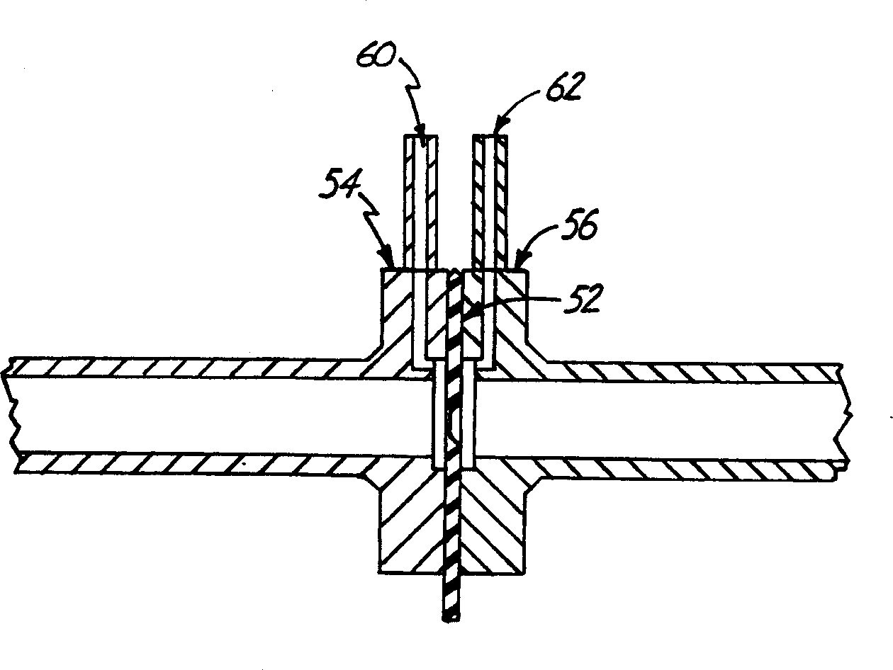
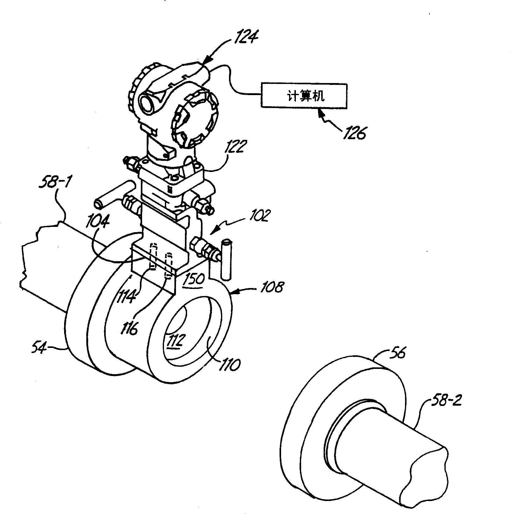
[0018] Figure 3-4 is an environmental depiction of one embodiment of a process flow device 100 of the present invention, including an instrument base 102 , first and second pressure orifice channels 104 , 106 and a differential flow plate 108 . The differential flow plate 108 includes a fluid conduit 110 supporting a fluid barrier 112 and first and second pressure holes 114, 116 (in Figure 4 briefly shown in ).

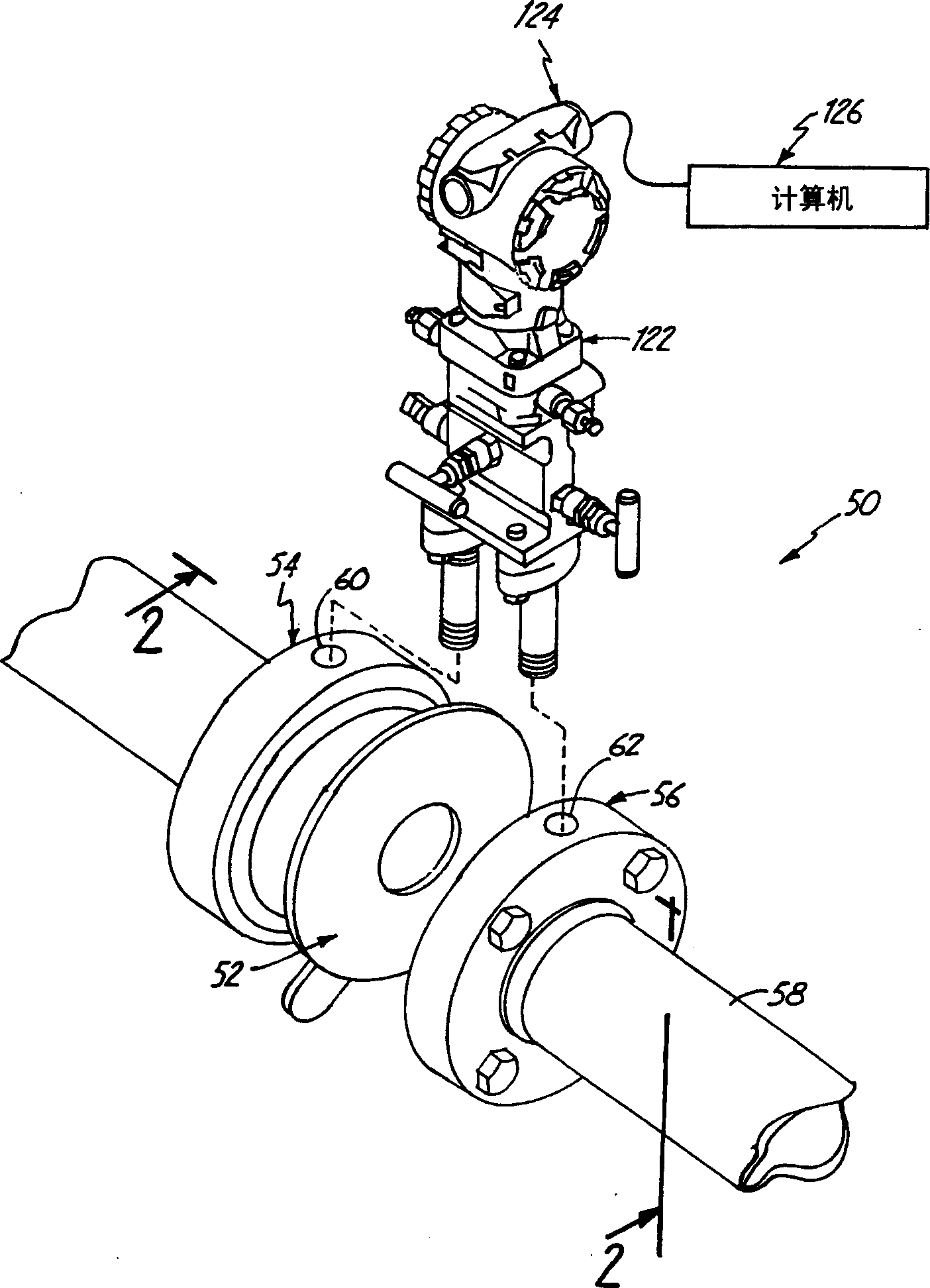
[0019] Such as Figure 4 As briefly shown, the instrument base 102 supports a processing instrument 120 . exist Figure 3-5 and 7, the processing instrument 120 includes a pressure sensor module 122 for isolating the differential pressure and a transmitter 124 for transmitting the processed data to a computer or readout device 126 (such as image 3 shown). A transmitter 124 or any other suitable readout device is capable of sensing process parameters and outputting the relevant output through the process loop to a control room or computer 126 so that the proces...


PUM


Abstract

A process flow device, said flow device (100) comprising a differential flow plate 108 insertable between tube sections 58-1, 58-2, the differential flow plate 108 comprising a support fluid barrier (112) Fluid conduit (110) pressure holes (114, 116). The fluid conduit (110) includes a seamless connection surface (154) between the fluid barrier (112) and the pressure holes (114, 116), so as to reduce the non-attributable pressure difference between the pressure difference holes (114, 116). pressure loss, and reduces on-site installation workload, including pressure testing of various pressure connections.

Description

technical field [0001] This invention relates to the process measurement and control industry. The process measurement and control industry utilizes process parameter transmitters to remotely monitor process parameters of fluids such as slurries, liquids, steam, gases, chemicals, pulp, petroleum, pharmaceuticals, food and other food producing crops. Process parameters include pressure, temperature, flow, water level, turbidity, density, concentration, chemical composition and other properties. Background technique [0002] figure 1 is an exploded view of an existing process flow device 50 for measuring process parameters such as differential pressure and flow. Such as figure 1 Flow plate 52 is shown sandwiched between flanges 54 , 56 on the fluid passage to create a pressure differential around the restriction for measuring the flow rate of fluid through tube 58 . The pressure differential near the point of flow restriction is measured at pressure ports 60,62. Such as ...

Claims


Application Information

Patent Timeline
Patent Type & Authority Applications(China)
IPC IPC(8): G01F1/40G01F1/42
CPCG01F1/42
Inventor 劳威尔·克莱文
Owner ROSEMOUNT INC
Why Eureka
Try Eureka