
Clutch assembly

A clutch and assembly technology, applied in clutches, friction clutches, fluid-driven clutches, etc., can solve the problems of complex and expensive clutch assemblies

Inactive Publication Date: 2002-08-21
SCHAEFFLER TECH AG & CO KG
View PDF6 Cites 21 Cited by
  • Summary
  • Abstract
  • Description
  • Claims
  • Application Information

AI Technical Summary

Problems solved by technology

However, these clutch assemblies are very complex and therefore expensive, and also require a very complex operating system for structural reasons

Method used


Image

  • Clutch assembly
  • Clutch assembly
  • Clutch assembly

Examples


Embodiment Construction

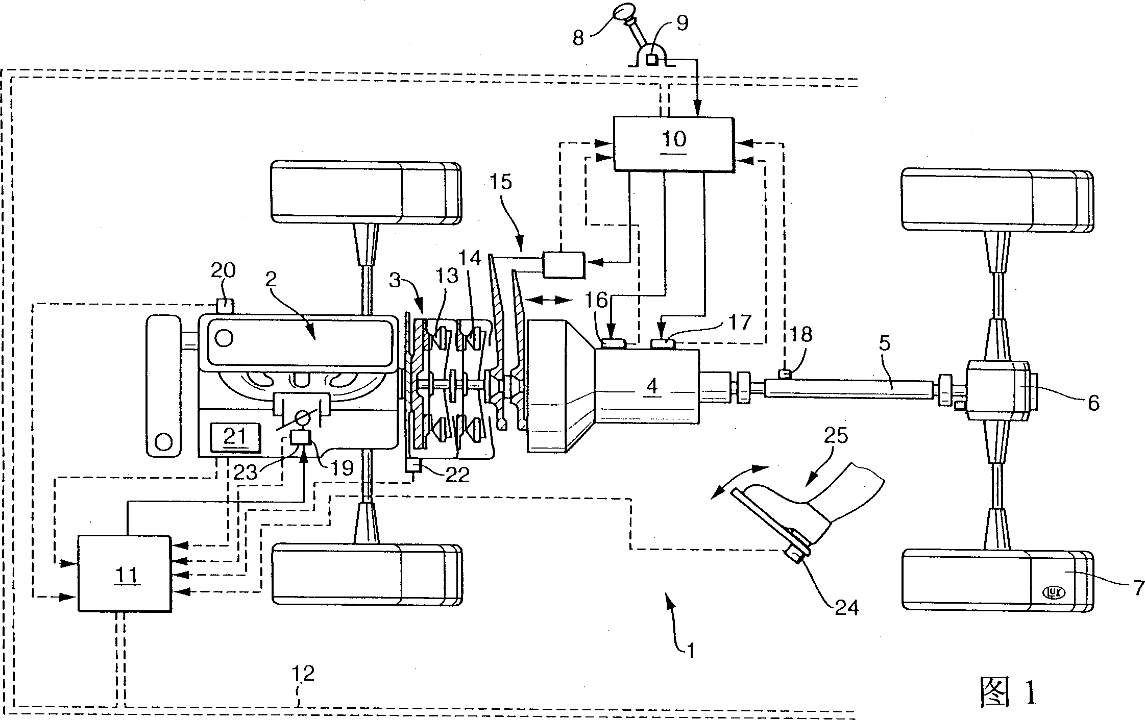
[0023] Figure 1 shows a car 1 with a transmission line, which includes an engine 2, a clutch assembly 3 and a gearbox 4 composed of an internal combustion engine. The wheels 7 of the automobile 1 are driven via a transmission shaft 5 and a differential 6. In its meaning, it can of course also be a car with one or more other driven axles.

[0024] Also shown here is a shift selection device 8 with a sensor 9 such as a shift lever, and a control device 10, 11 in the form of a block diagram. The control devices 10, 11 may be constructed as a unit, or may be designed in a local area separated in structure and / or function. If the control devices 10 and 11 are designed in local areas separated in structure and / or function, they can be connected to each other via a CAN bus 12 or other electrical connection methods for data exchange, for example. The control devices 10 and 11 are used, for example, to control the automatic operation of the gearbox 4 and / or to control the clutches 13, 14 o...


PUM


Abstract

The present invention relates to a clutch unit is for torque transmission between engine and gear, and contains a rotary vibration damper and at least one friction clutch.

Description

Technical field [0001] The invention relates to a clutch assembly for transmitting torque between an engine and a gearbox. The present invention particularly relates to such a clutch assembly, which includes at least one torsional vibration damper and at least one friction clutch, through which the engine and the gearbox can be connected and separated from each other in a transmission manner. Background technique [0002] For example, a clutch assembly with two friction clutches is known from DE2830659 A1. However, these clutch assemblies are very complex in structure and therefore expensive, and for structural reasons also require a very complex operating system. Summary of the invention [0003] The task of the present invention is to provide a clutch assembly of the type mentioned at the beginning, which has good functions and a simple structure and can be manufactured inexpensively. In addition, the clutch assembly according to the present invention can also be operated in a...

Claims


Application Information

Patent Timeline
IPC IPC(8): B62D65/10F16D21/06F16D25/08F16D25/10
CPCF16D2021/0669Y02T10/76F16D21/06F16D25/10F16D25/087
Inventor 塞巴斯蒂安·贝内东罗尔夫·迈因哈德
Owner SCHAEFFLER TECH AG & CO KG
Learn More