Eureka AIR delivers breakthrough ideas for toughest innovation challenges, trusted by R&D personnel around the world.

Current transformer used on composite type gas insulation switch

A gas-insulated switch and composite technology, which is applied in the field of converters, can solve problems such as converter configuration, and achieve the effect of increasing the degree of freedom of design.

Inactive Publication Date: 2002-06-12
KK TOSHIBA
View PDF0 Cites 2 Cited by
  • Summary
  • Abstract
  • Description
  • Claims
  • Application Information

AI Technical Summary

Problems solved by technology

[0011] However, feed-through converters used in conventional gas insulated switchgears with analog current outputs (usually rated secondary output 1A or 5A) can only be incorporated on the ground potential side in consideration of insulation. Converter cannot be configured in Figure 11 Both sides of the breaker of the compound gas insulated switchgear shown

Method used


Image

  • Current transformer used on composite type gas insulation switch
  • Current transformer used on composite type gas insulation switch
  • Current transformer used on composite type gas insulation switch

Examples


no. 2 Embodiment

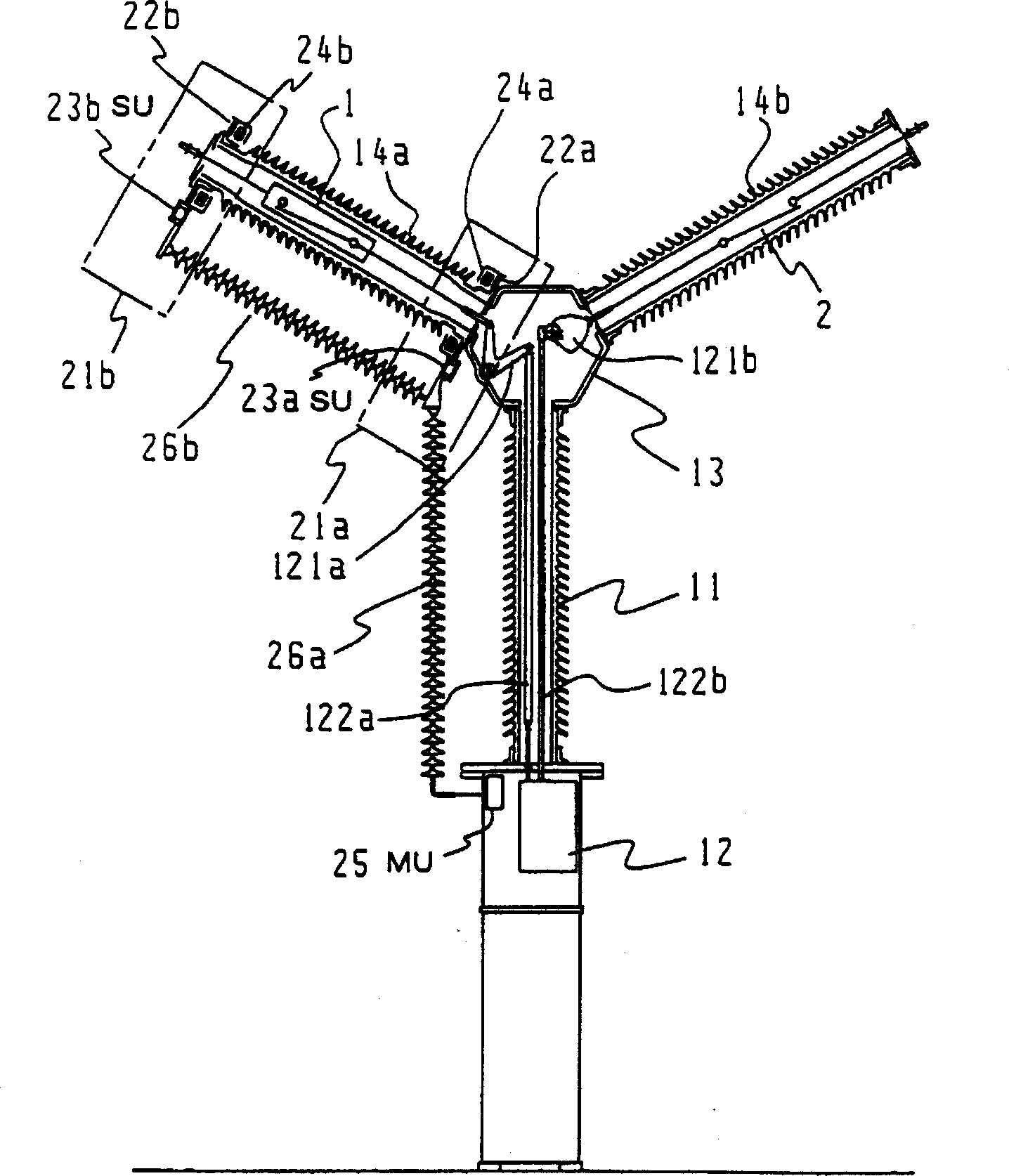
[0077] Figure 5 It is a structural diagram of a current transformer for a composite gas insulated switchgear according to a second embodiment of the present invention.

[0078] Figure 5 In the shown composite gas insulated switchgear, the operating device 12 is connected to the lower end of the hollow columnar insulating support 11, and the metal container 13 for accommodating the driving connection parts 121a and 121b is connected to the upper end. On the upper portion of the metal container 13, a first porcelain tube 14a, a second porcelain tube 14b, and a third porcelain tube 14c are connected in a trident shape. The breaker 1 is accommodated in the first porcelain tube 14a, the circuit breaker 2a is accommodated in the second porcelain tube 14b, and the breaker 2b is accommodated in the third porcelain tube 14c. These circuit breakers 1 and circuit breakers 2 a and 2 b are connected in series in a metal container 13 . These circuit breakers 1 and circuit breakers 2a a...


PUM


Abstract

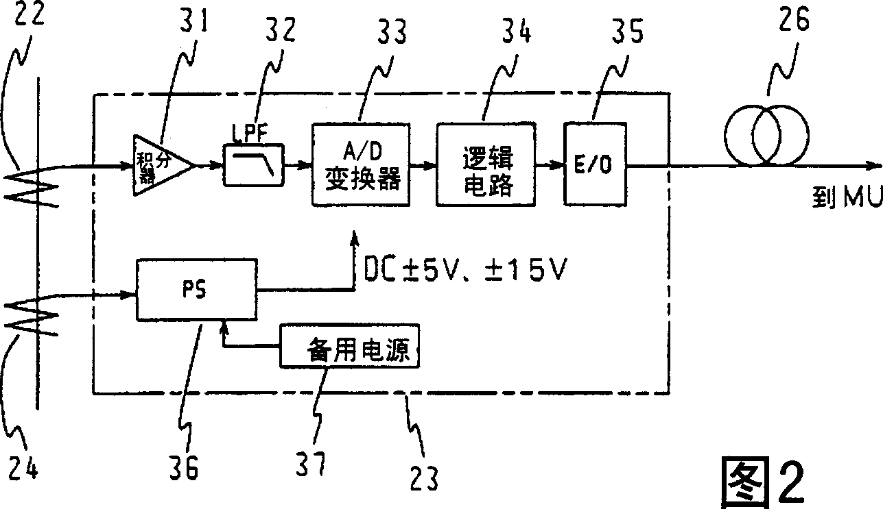
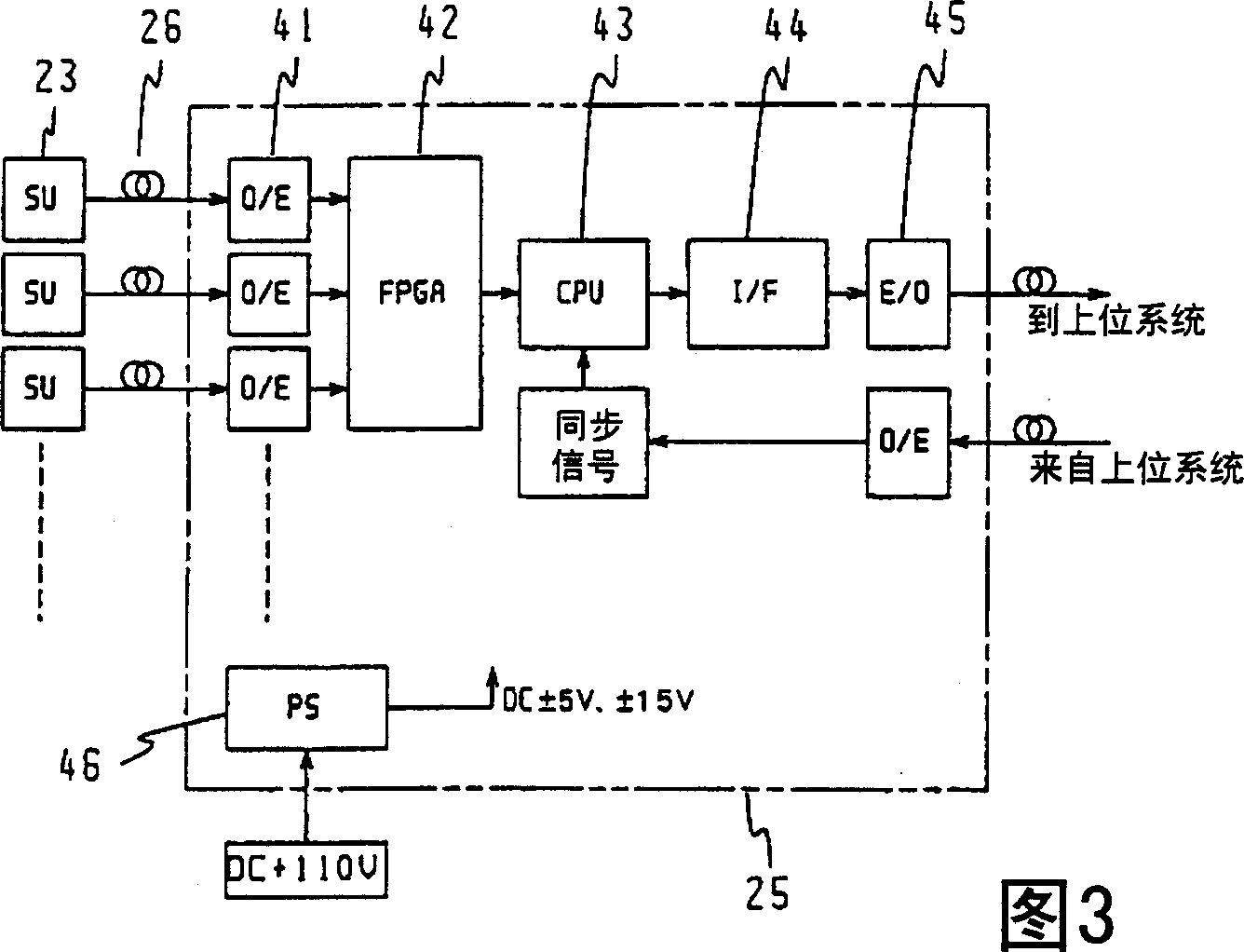
The present invention provides a current transformer for a compound-type gas-insulated switchgear which can be arranged on either side of a circuit-breaker. To the lower end of an insulating support structure 11, an operating apparatus 12 is connected, and to the upper end a metal container 13 is connected. To the upper part of the metal container 13, a first ceramic bushing 14a, in which a circuit-breaker 1 is housed and a second porcelain bushing 14b in which a disconnector 2 is housed, are connected. The circuit- breaker 1 and the disconnector 2 are opening / closing-operated by the operating apparatus 12. Current transformers 21a, 21b are set at both ends of the ceramic bushing 14a. The current transformers 21a, 21b are composed of current detect means 22a, 22b, sensor units 23a, 23b, power-feeding current transformers 25a, 24b and an integrating unit 25. The integrating unit is set in a housing part for the operating apparatus, and the sensor units 23a, 23b and integrating unit are connected to each other with insulators 26a, 26b which house optical fibers.

Description

technical field [0001] The present invention relates to a converter for measuring the AC current of a main circuit of a gas insulated switchgear for electric power. Background technique [0002] Generally, in an air substation, the busbars and iron towers have a long service life, and the busbars and iron towers are relatively seldom replaced when the switchgear is replaced. Therefore, in order to effectively use the air-insulated busbars, the switchgear is often replaced with a high-performance, high-reliability switchgear. In order to meet this demand, a composite type gas insulated switchgear has been proposed in the past. [0003] Below, use Figure 9 with Figure 10 , to explain the structure of the general line circuit of the air substation of the double bus system. [0004] Figure 9 with Figure 10 Respectively represent the structure of the machine and the single-line wiring diagram. In the air substation, a circuit breaker 1 is arranged on the line side circui...

Claims


Application Information

Patent Timeline
Patent Type & Authority Applications(China)
IPC IPC(8): H02B13/02G01R15/14H02B13/065
CPCY10T307/527G01R15/14H02B13/065H01H33/027
Inventor 斋藤实
Owner KK TOSHIBA
Why Eureka
Eureka Blog
Learn More