Antenna with an electric conductive layer and dual band emitter therewith

A technology of conductive layer and transmitter, which is applied in the direction of electrical short antennas, antennas suitable for movable objects, antennas, etc., can solve the problems of high cost, difficulty in obtaining resonant frequency, and large total antenna thickness, and achieve easy matching Effect

Inactive Publication Date: 2002-03-06
ALCATEL LUCENT SAS
View PDF3 Cites 12 Cited by
  • Summary
  • Abstract
  • Description
  • Claims
  • Application Information

AI Technical Summary

Problems solved by technology

Its specific disadvantage is that the cumulative thickness of the insulator substrate between the layers makes the overall thickness of the antenna too large
[0033] In general, the disadvantage of the prior art antennas described above is that it is difficult and expensive to obtain the desired resonant frequency while coupling the individual resonances well to one signal processor

Method used


Image

  • Antenna with an electric conductive layer and dual band emitter therewith
  • Antenna with an electric conductive layer and dual band emitter therewith
  • Antenna with an electric conductive layer and dual band emitter therewith

Examples


Embodiment Construction

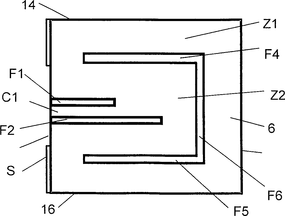
[0046] Such as figure 2 As shown, a resonant structure based on the antenna of the present invention comprises the following components known in the art:

[0047] - An insulator substrate 2 having two opposing main surfaces which respectively form a bottom surface and a top surface and which extend in horizontal directions DL and DT, wherein the directions may depend on the relevant antenna area. As mentioned above, the substrate can have various shapes.

[0048] - A bottom conductive layer extending at least over the entire bottom surface of the substrate and constituting a ground plane 4 of the antenna. figure 2 Only a portion of this layer beyond this bottom surface is shown.

[0049] - a top conductive surface as shown in FIGS. 1-3 extending to a region of the top surface of the substrate above the ground layer 4 to form a patch 6 . Usually a patch has a length and a width extending in horizontal longitudinal DL and horizontal transverse direction DT respectively, and i...


PUM


Abstract

The antenna of said transmitter is a microstrip antenna. A rear edge of its patch is provided with a short circuit by means of which a quarter-wave primary resonance can be excited by a coplanar line formed by two coupling slots in an area. Separator slots separate said area from another area in which a secondary resonance can be established at twice the frequency of the primary resonance from a slotted line extending one slot of the coplanar line. The invention applies in particular to the production of a dual-mode mobile telephone to the GSM and DCS standards.

Description

technical field [0001] The present invention relates to radio transmitters, in particular mobile telephones, and more particularly to antennas incorporated in such transmitters and comprising a conductive layer. Background technique [0002] Such antennas consist of a patch, which is usually obtained by etching a metal layer. Such antennas are known as microstrip patch antennas. [0003] Microstrip technology is a planar technology used to manufacture transmission lines for transmitting guided or transmitted signals and antennas for connecting such lines to radiating waves. This technique uses conductive patches and / or strips formed on the top surface of a thin insulator substrate. The conductive layer extends to the underlying surface of the substrate and constitutes a ground plane for the wiring or antenna. A patch is usually wider than a strip and its shape and size are important characteristics of the antenna. The substrate is usually a flat rectangular sheet of cons...

Claims


Application Information

Patent Timeline
Patent Type & Authority Applications(China)
IPC IPC(8): H01Q13/08H01Q1/24H01Q1/38H01Q5/00H01Q5/10H01Q5/371H01Q9/04
CPCH01Q9/0421H01Q9/045H01Q5/0058H01Q1/243H01Q5/371
Inventor 查尔斯·N·考姆让-菲利普·库普兹
Owner ALCATEL LUCENT SAS
Why Eureka
Try Eureka