Image recording/reproducing device and method disc and image reproducing device
A technology of a video recording and reproducing device, applied in the directions of digital recording/reproducing, data recording, recording information storage, etc., can solve problems such as time-consuming, processing time, metadata user waiting, etc.
- Summary
- Abstract
- Description
- Claims
- Application Information
AI Technical Summary
Problems solved by technology
Method used
Image

Examples
Embodiment 1
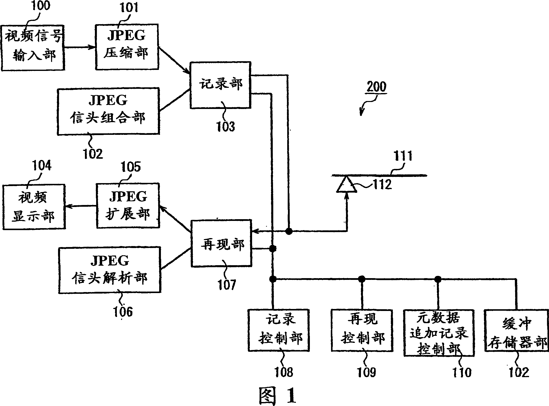
[0078] FIG. 1 is a block diagram of a video recording and reproducing apparatus according to Embodiment 1 of the present invention. If the release button (not shown) is pressed, the recording control unit 108 performs JPEG compression on the still image generated in the video signal input unit 100 in the JPEG compression unit 101, and the DQT marker segment, The DHT marker segment, SOF marker segment, SOS marker segment, compressed data and EOI marker are recorded on the optical disc 111 . Next, the recording control unit 108 activates the JPEG header combining unit 102 to record the SOI marker, APP1 marker segment, APP5 marker segment, and COM (comment) marker segment. Furthermore, the recording control unit 108 records file management information so that each marker segment of SOI, APP1, APP5, and COM, each marker segment of DQT, DHT, SOF, and SOS, compressed data, and EOI segment are handled as one file. On the other hand, the metadata additional recording control unit 110...
Embodiment 2
[0092] FIG. 6 shows an example in which the data structure shown in FIG. 3 is slightly changed. The difference is that the data arrangement of the SOF flag segment is shifted from area B (second area) to area A (first area). In the DCF basic file, only the SOF flag segment describes the number of pixels and color samples (4:2:2 / 4:2:0, etc.) of the recorded still image. Thereby, when searching and sorting with the number of pixels and the number of color samples throughout a plurality of JPEG files, since the SOF marker segment is stored in the buffer memory, compared with the case where there is a considerable part of the area B (the second area), the improvement can be significantly improved. processing time. Therefore, for example, when the worst-case movement time at the time of search is 1 second, the processing time can be reduced by the same number of seconds as the maximum number of search target files. In addition, the FID is not recorded together with the part (phys...
Embodiment 3
[0094] Fig. 7 shows the situation of recording a DCF basic file including APP1 marker segment and APP2 marker segment according to the DCF specification. In the APP2 flag segment, information for facilitating the conversion from the DCF basic file to the FlashPix file format is stored. Since the data size is often larger than APP1 (for example, 64K bytes), it is difficult to become a search object and the area A (the first area) is limited, so the APP2 marker segment should not be stored in a considerable part of the area A (the first area). Therefore, the data size of APP2 on the compressed area A (the first area) is recorded up to the sector boundary (thus, the data size of APP2 is usually less than 1 sector), and the rest is recorded in the area B (the second area). part. At this time, the same APP5 marker segment and COM marker segment as in the first embodiment are recorded up to the sector boundary. When adding the APP4 flag segment, it can be configured behind the COM...
PUM
 Abstract
Description
Claims
Application Information
 - R&D
- Intellectual Property
- Life Sciences
- Materials
- Tech Scout
- Unparalleled Data Quality
- Higher Quality Content
- 60% Fewer Hallucinations
Browse by: Latest US Patents, China's latest patents, Technical Efficacy Thesaurus, Application Domain, Technology Topic, Popular Technical Reports.
© 2025 PatSnap. All rights reserved.Legal|Privacy policy|Modern Slavery Act Transparency Statement|Sitemap|About US| Contact US: help@patsnap.com