
Electricity generating device by temperature difference

A power generation device, temperature difference technology, applied to generators/motors, electrical components, thermoelectric devices that only use the Peltier or Seebeck effect, etc., can solve problems that have not been seen in the market, and the relative temperature difference value is not easy to achieve And other issues

Inactive Publication Date: 2007-08-01
朱宝平 +1
View PDF6 Cites 4 Cited by
  • Summary
  • Abstract
  • Description
  • Claims
  • Application Information

AI Technical Summary

Problems solved by technology

[0002] Cooling chips are widely used in aerospace and electrical appliances. In the past, power was input into the cooling chip to make the cooling chip form a high and low temperature output. However, in recent years, the cooling chip has made more use of the temperature difference and the circuit It is connected to the rail to form a thermoelectric effect, so it can obtain electric energy on the connecting circuit and then use it. However, although this technology has long been known to the world, it is not easy to achieve a certain relative temperature difference in practice, and there are problems that cannot be implemented or In the case of poor efficiency in implementation, there are no devices that have been seen in the city.

Method used


Image

  • Electricity generating device by temperature difference
  • Electricity generating device by temperature difference
  • Electricity generating device by temperature difference

Examples


Embodiment Construction

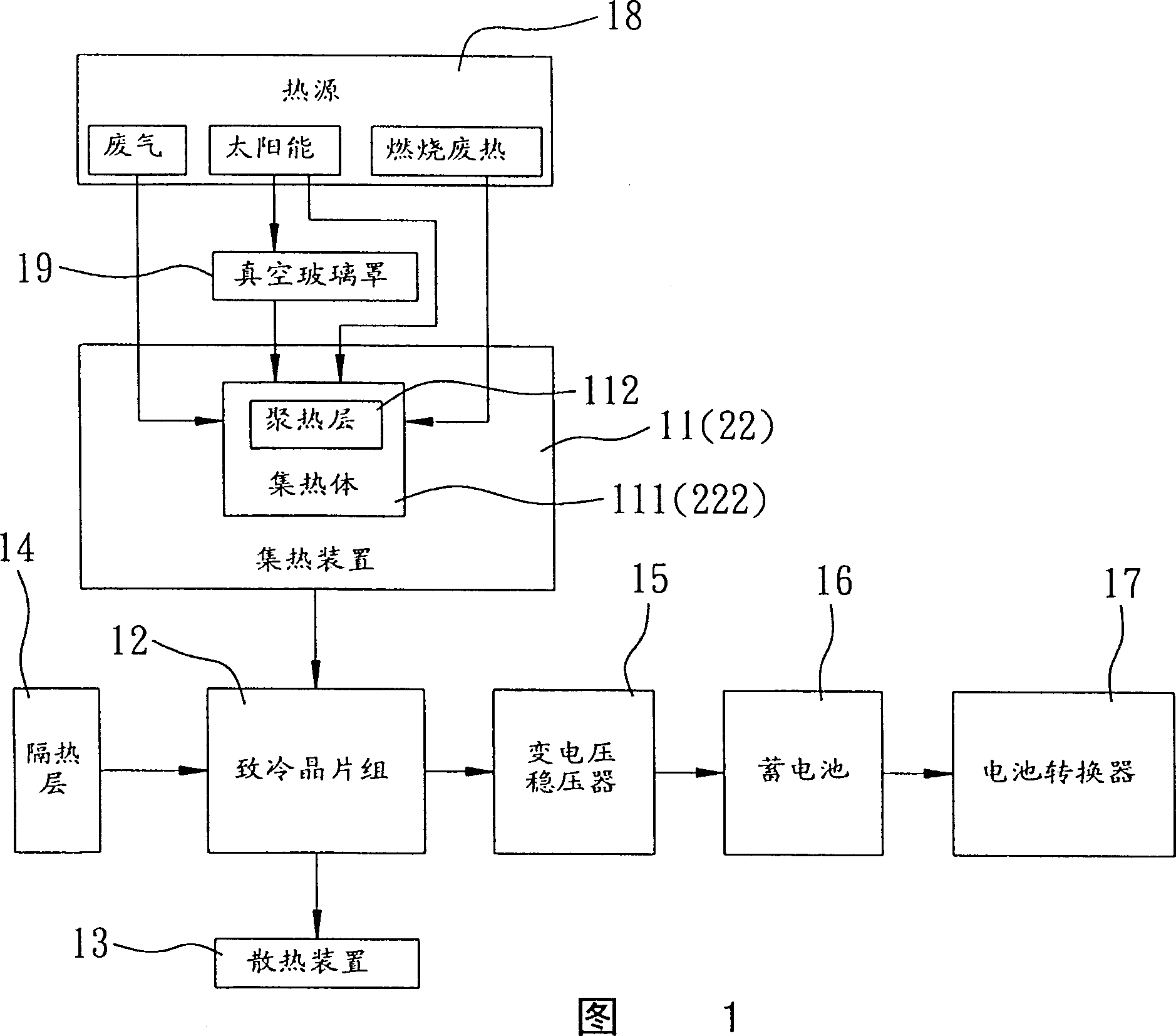
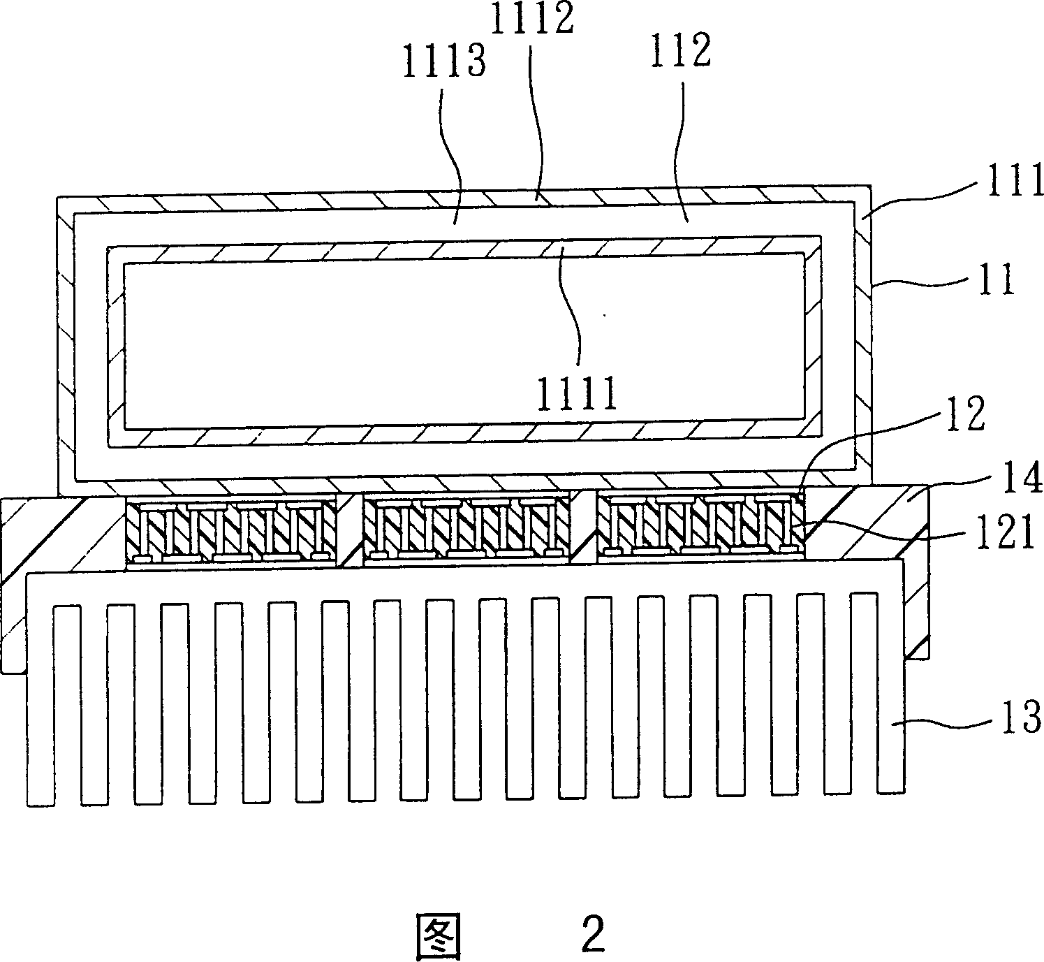
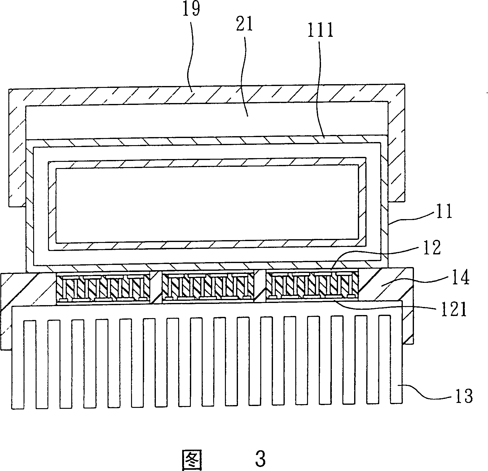
[0017] As shown in Figures 1 and 2, it is the first preferred embodiment of the thermoelectric power generation device of the present invention. A voltage stabilizer 15, a storage battery 16, a power converter 17, and a heat source 18 providing the heat collector 11, wherein:

[0018] The heat collection device 11 has a heat collector 111 capable of absorbing heat and raising the temperature, and a heat collection layer 112 arranged on the heat collector 111. The heat collector 111 is surrounded by an inner wall 111 and an outer wall 1112. It is set as a chamber 1113, and the heat accumulating layer 112 is formed by filling or spraying the interior of the chamber 1113 with heat-absorbing or exothermic heat-conducting materials, so that the interior of the heat collector 111 has the effect of rapid heat conduction and heat accumulation .

[0019] The heat conduction mode means of the heat collecting device 11 can be roughly divided into the following four types according to th...


PUM


Abstract

The invention is a thermal electric generating device, mainly using a heat collector able to absorb thermal energy to transfer the thermal energy to a cooling wafer group, so as to make the wafer group able to generate DC by thermoelectric effect to be stored in an accumulator, or then converting DC into AC by power supply converter for general electric appliances, in addition the heat collector can quickly conduct heat by heat collecting body and maintain thermal energy, besides the cooling wafer group can continuously send out thermal energy by cooling device, which can maintain the temperature difference between the heat collecting body and cooling wafer group to continuously produce electric energy.

Description

(1) Technical field [0001] The invention relates to a thermoelectric power generation device, in particular to a power generation device that generates voltage for use by means of thermoelectric effect between a heat collection device and a cooling chip group. (2) Background technology [0002] Cooling chips are widely used in aerospace and electrical appliances. In the past, power was input into the cooling chip to make the cooling chip form a high and low temperature output. However, in recent years, the cooling chip has made more use of the temperature difference and the circuit It is connected to the rail to form a thermoelectric effect, so it can obtain electric energy on the connecting circuit and then use it. However, although this technology has long been known to the world, it is not easy to achieve a certain relative temperature difference in practice, and there are problems that cannot be implemented or Under the situation that the efficiency is not obvious under ...

Claims


Application Information

Patent Timeline
Patent Type & Authority Patents(China)
IPC IPC(8): H01L35/28H02N11/00H10N10/10
Inventor 骆俊光
Owner 朱宝平
Learn More