Comber for rotary clamp bed

A combing machine and combing technology, applied in the direction of combing machines, textiles, papermaking, fiber processing, etc., can solve the problems of airflow interference, loud noise, machine body vibration, etc., and achieve improved carding degree, good machine sealing, dynamic The effect of distance reduction

Inactive Publication Date: 2007-08-01
吕恒正
View PDF8 Cites 0 Cited by
  • Summary
  • Abstract
  • Description
  • Claims
  • Application Information

AI Technical Summary

Problems solved by technology

The isolation plate and sealing cover are installed on the frame to effectively control the airflow and make the fiber mesh better bonded, thereby solving technical problems such as body vibration, loud noise, and airflow interference caused by the high-speed reciprocating motion of the clamp bed assembly.

Method used


Image

  • Comber for rotary clamp bed
  • Comber for rotary clamp bed
  • Comber for rotary clamp bed

Examples


Embodiment Construction

[0044] The specific implementation, structure, features and effects provided by the present invention will be described in detail below in conjunction with the accompanying drawings and preferred embodiments.

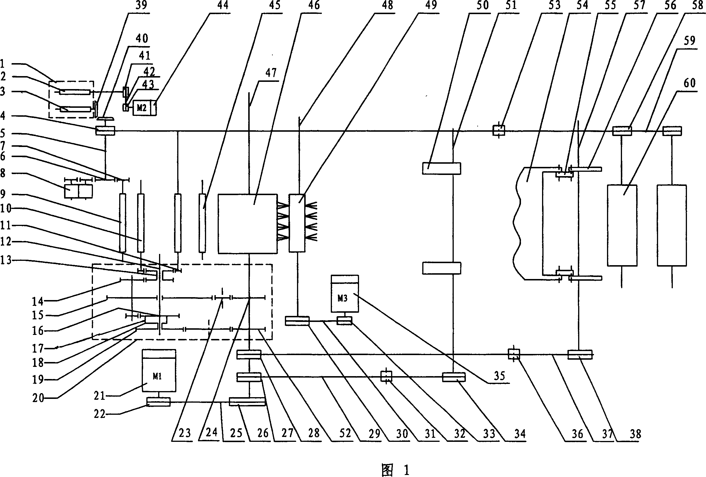
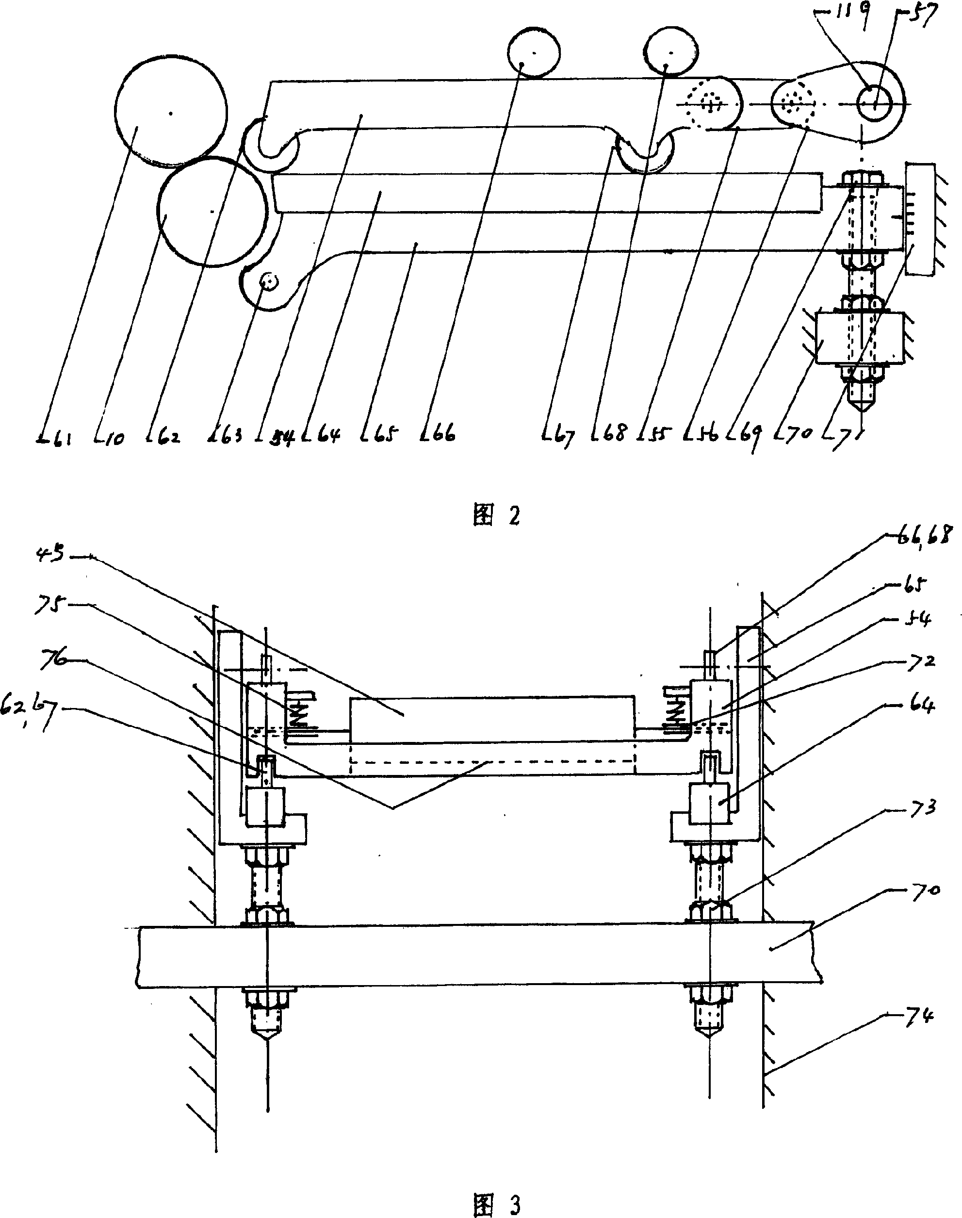
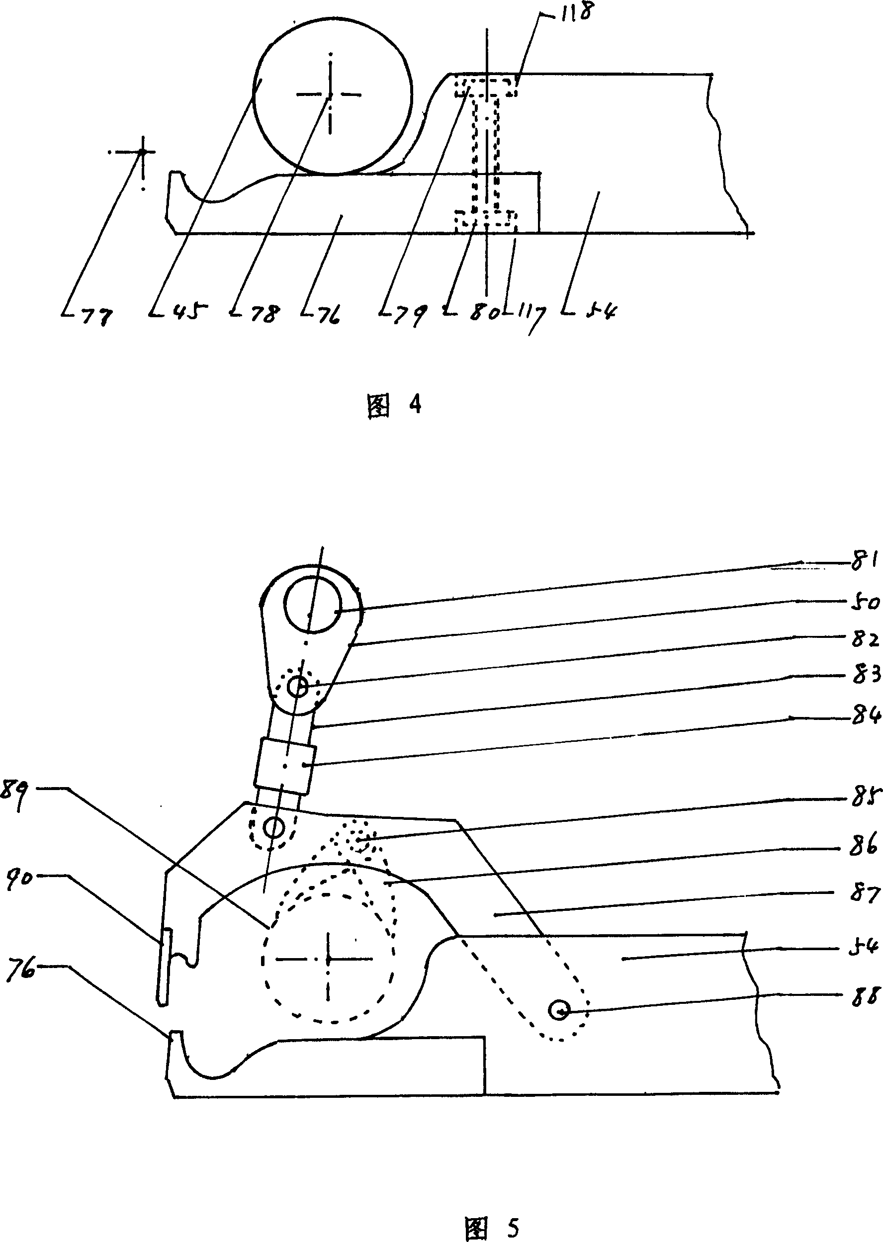
[0045] As shown in Figure 1-8. The present invention provides a combing machine with a rolling pincer bed, which is composed of eight combing heads. The structure of one combing head is shown in the accompanying drawings as an example to illustrate its structural relationship.

[0046] Please refer to Fig. 1, the main motor 21 (M1) transmits the power to the cylinder shaft 47 through the sheaves 22, 26 and the triangular belt 25, and the cylinder shaft transmits the power through the sprocket 28, 38 tension wheel 36 and the toothed belt 37 Assigned to the eccentric shaft 57, the eccentric sleeve 56 of the eccentric disk 119 sleeved on the 57 drives the clamp bed 54 to reciprocate through the hinged connecting rod 55.

[0047] The cylinder shaft 47 distributes the power...


PUM


Abstract

A combing machine equipped with a rotary tong-basement consists of a frame, a motor, a gear-box and a combing part. The rotary tong-basement, arranged on the combing part and pivoted onto an eccentric transmission sleeve via a linkage bar, can move reciprocally on a slide bed on the frame. The eccentric transmission sleeve is installed on a disc on a eccentric driving shaft connected with the motor via a transmission mechanism. A triangular arm is arranged on the rotary tong-basement, with the upper tong plate at the front end of the triangular arm. Feeding rollers with bearings are installed on the tong-basement. A lower tong plate and top comb are fixed on the front end of the tong-basement. The upper tong plate is also pivoted with a connecting lever, of which the other end is pivoted on an eccentric calender sleeve, which is also arranged on an eccentric disc of an eccentric calender shaft that is connected with the motor via a transmission mechanism. The said machine has high speed, less vibration and noise, with high use ratio of resource and improved air flow condition.

Description

technical field [0001] The invention belongs to the field of textile machinery and relates to a combing machine, in particular to a combing machine with a rolling pincer bed. Background technique [0002] In the field of cotton spinning machinery, at present, all types of combers at home and abroad are of the pincer bed swing type. CN2500693Y patent discloses a kind of combing machine with fixed pincer bed. The combing machine with swinging pincer bed has a long history. Various textile machinery manufacturers have invested a lot of manpower, material resources, and financial resources to work hard on improving the number of pincers of the combing machine, such as: reducing the weight of the pincer bed components as much as possible; The swing range of the bed; improving the structure of the nipper pressing system and the like, although considerable progress has been made, the current combing machine has never left the swinging mode of the nipper bed. And the contradiction...

Claims


Application Information

Patent Timeline
Patent Type & Authority Patents(China)
IPC IPC(8): D01G19/16
Inventor 吕恒正
Owner 吕恒正
Why Eureka
Try Eureka