
Raman optical fiber enlarger

A technology of fiber amplifiers and fiber lasers, which is applied to lasers, laser components, phonon exciters, etc., can solve problems such as cost hindering Raman fiber amplifier constraints, and achieve superior cost performance, wide cost overhead, and improved heat dissipation mechanism Effect

Inactive Publication Date: 2007-07-25
武汉华工飞腾光子科技有限公司
View PDF5 Cites 0 Cited by
  • Summary
  • Abstract
  • Description
  • Claims
  • Application Information

AI Technical Summary

Problems solved by technology

However, the cost problem has always been a restrictive factor hindering the application of Raman fiber amplifiers in more optical communication fields

Method used


Image

  • Raman optical fiber enlarger
  • Raman optical fiber enlarger

Examples


Embodiment Construction

[0009] The present invention will be further described below in conjunction with the embodiments and accompanying drawings.

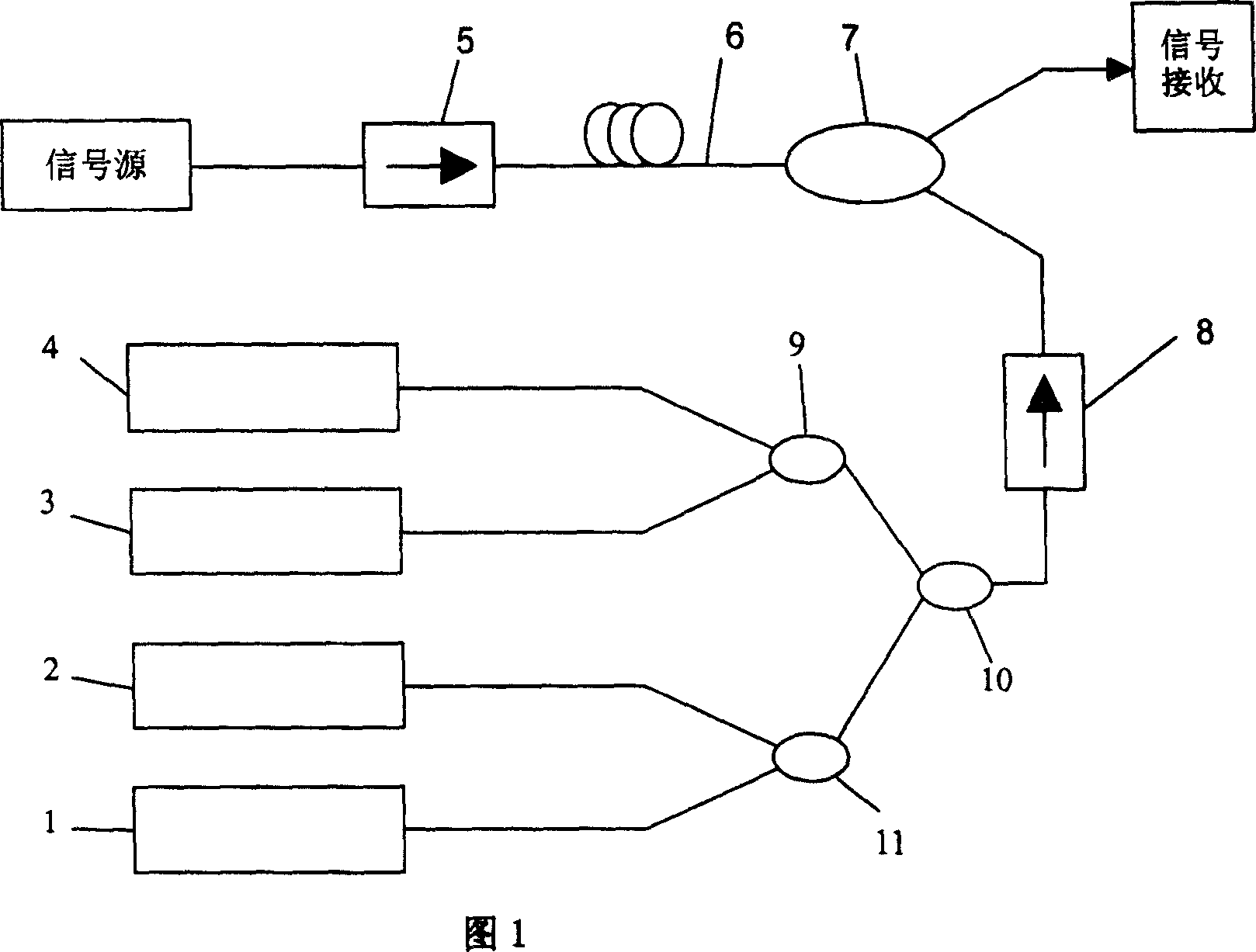
[0010] The structure of the present invention is shown in FIG. 1 : it consists of four Raman fiber laser modules with different output wavelengths, three pumping optical wavelength division multiplexers with different input channel center wavelengths, and a pumping optical isolator 8 . Among them: Raman fiber laser modules 1, 2, 3, and 4 are used as pump laser modules, and are injected into the pump / signal wavelength division multiplexer through the pump optical wavelength division multiplexer 9, 10, 11 and the pump optical isolator 8 7. Then inject the transmission fiber 6 through the output end of the pump / signal wavelength division multiplexer 7, and perform Raman amplification on the C+L band signal light passing through the signal optical isolator 5.

[0011] The output wavelengths of the above-mentioned Raman fiber laser modules 1, 2, 3, and 4 are...


PUM


Abstract

Raman optical fiber amplifier is composed of four pieces of Raman optical fiber laser modules of outputting different wavelength, three pieces of pump light wavelength division multiplexer in different central wavelengths of input channel, and pump opto-isolator. Raman optical fiber laser modules as pump laser modules through pump light wavelength division multiplexes (9), (10), (11) and pump opto-isolator inject into pump / signal wavelength division multiplexer (7). Output from pump / signal wavelength division multiplexer (7) is injected to transmission optical fiber. Finally, Raman amplification is carried out for signal light in C+L band being passed through signal opto-isolator. Advantages are: stable and reliable performance, high Raman conversion efficiency, and favorable ratio of performance, wider gain bandwidth, quick response speed and flexible configuration.

Description

technical field [0001] The invention relates to an application device in the field of optical communication, in particular to a Raman fiber amplifier. Background technique [0002] Raman fiber amplifier is the key technology to realize high-speed, large-capacity, long-distance optical fiber communication system. The gain medium of the Raman fiber amplifier is a channel transmission fiber, which does not require a special transmission medium; its amplification wavelength only depends on the pump wavelength, and can amplify the signal of any communication window; it can be realized by optimizing the configuration of different pump wavelengths and pump power Broadband flat amplification; its distributed amplification characteristic has low noise, which can improve the system power margin, increase the signal rate and transmission distance, and can also solve the nonlinear damage of multi-channel and long-distance transmission. However, the cost problem has always been a restri...

Claims


Application Information

Patent Timeline
Patent Type & Authority Patents(China)
IPC IPC(8): H01S3/00
Inventor 张敏明刘德明王英胡必春
Owner 武汉华工飞腾光子科技有限公司
Learn More