Pressing unit for separating the diecut blanks of a sheet

A pressing device, die-cutting technology, applied in the direction of peeling device, sending objects, transportation and packaging, etc., can solve the problem of long pressure track

Active Publication Date: 2007-07-11
BOBST SA
View PDF6 Cites 0 Cited by
  • Summary
  • Abstract
  • Description
  • Claims
  • Application Information

AI Technical Summary

Problems solved by technology

The connecting means of the rods are fastened with two screws each, which means that the assembly of the pressure rail takes a long time

Method used


Image

  • Pressing unit for separating the diecut blanks of a sheet
  • Pressing unit for separating the diecut blanks of a sheet
  • Pressing unit for separating the diecut blanks of a sheet

Examples


Embodiment Construction

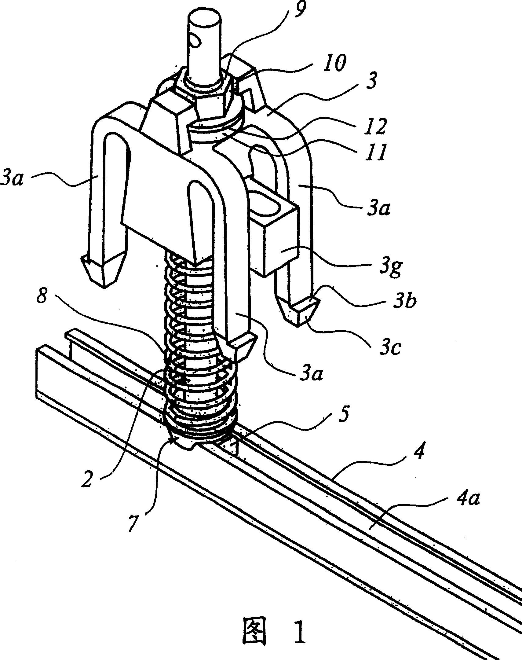
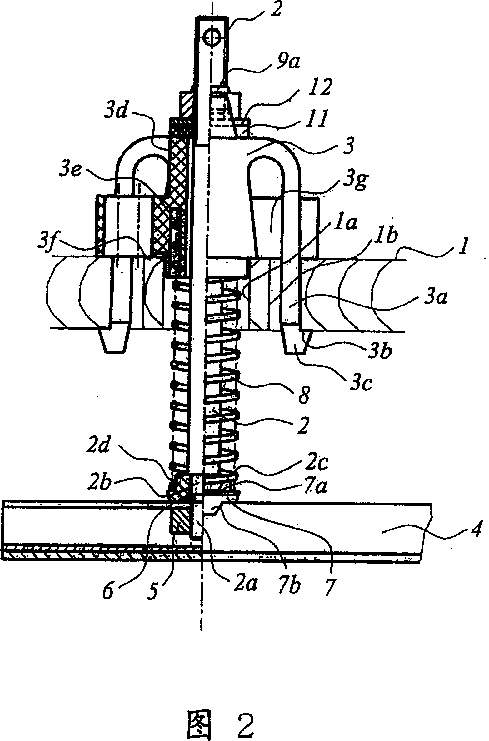
[0019] The pressing device of the present invention comprises a horizontal upper support 1, in this embodiment, the upper support 1 is made of a wooden board with a hole 1a for moving the sliding rod 2, only drawn in the figure Out came a slide bar. The sliding rod 2 is mounted so as to slide in a connecting device 3 . The connecting device 3 comprises four deformable clamping claws 3 a which pass through four holes 1 b of the upper support 1 . These deformable clamping jaws 3a terminate in a bearing or stop surface 3b which extends towards the outside of the deformable clamping jaws 3a. Said bearing surface is adjacent to a locking surface 3c which is inclined towards the inside of said deformable claw 3a.

[0020] Since the deformable clamping jaws 3a are slightly inclined with respect to their free state in the clamping position of the support plate 1, when in the clamping position of the connecting device 3, the stop surface 3b is parallel to the support plate 1, ensuri...


PUM


Abstract

A pressing unit with a pressure rail interdependent with at least two parallel rods, the rods mounted for axially sliding between two end positions, through a horizontal upper support, via a connecting device. An elastic pull-back spring arranged between the support and the pressure rail likely maintains the rail in its most wide apart position from the horizontal upper support, defined by stops interdependent of the rods. The connecting device comprises a bearing surface against the upper side of the upper support and at least two deformable claws symmetrically arranged with respect to the longitudinal axis of the rod passage. The claws pass through two related passages through the support and the claws each comprise a bearing surface against the lower surface of the support.

Description

technical field [0001] The present invention relates to a pressing device for separating die-cut blanks of cardboard, the device comprising a pressure track associated with at least two sliding bars mounted so as to pass between two end positions through a horizontal upper support and slides through connecting means, which also includes elastic means between said support and said pressure rail to maintain the pressure rail in the position furthest from the horizontal upper support, whereby The farthest position is determined by the detents associated with the two sliding bars. Background technique [0002] When blanks or blanks are to be die cut from a large sheet of cardboard, the blanks or blanks are joined to the strips with very fine cardboard breaks created by very short die cut line breaks. In this way, the cardboard is fed to the lower support plate having the openings in the shape of the blank. In order to peel off the blanks from the cardboard, a hold-down device ...

Claims


Application Information

Patent Timeline
Patent Type & Authority Patents(China)
IPC IPC(8): B26D7/02B26D7/18B21D28/24B21D45/00B65H35/10
CPCB26D7/1818B65H35/10Y10T225/386B26D7/025Y10T225/393B21D28/24B21D45/00
Inventor 让-皮埃尔·斯泰纳
Owner BOBST SA
Why Eureka
Try Eureka