
Patsnap Eureka
For R&D, Patsnap Eureka makes reading and utilizing patents & technical documents easy.
Patsnap Eureka AIR
Designed for self-driven R&D workflows. Generate viable solutions, solve complex R&D challenges, empower your innovation with AI.

Patsnap Eureka Materials
Designed for material experts only. Revolutionize your material R&D, from search, analyze, to developing new materials.

TechResearch
Generate reliable direction feasibility study reports for your R&D in just a few steps.

TechSeek
Discover and master advanced knowledge NOW. Basics, ideas, possibilities, all at once.

TechMind
As an expert in R&D Theories, TechMind can generates customized viable solutions instantly.

TechRisk
Analyze your overall solution with one click, know your potential R&D risks in advance.

TechMonitor
Get weekly tech updates, stay abreast of the latest tech innovations and key insights.
Roller for spinning preparing machine
A technology for preparing machines and rollers, used in textile and papermaking, deburring devices, fiber processing, etc., can solve the problems of expensive subsequent processing, heavy roller weight, undesired bending stress, etc., to achieve short acceleration and braking time, driving The effect of low power and weight reduction
- Summary
- Abstract
- Description
- Claims
- Application Information
AI Technical Summary
Problems solved by technology
Method used
Image

Examples
Embodiment Construction
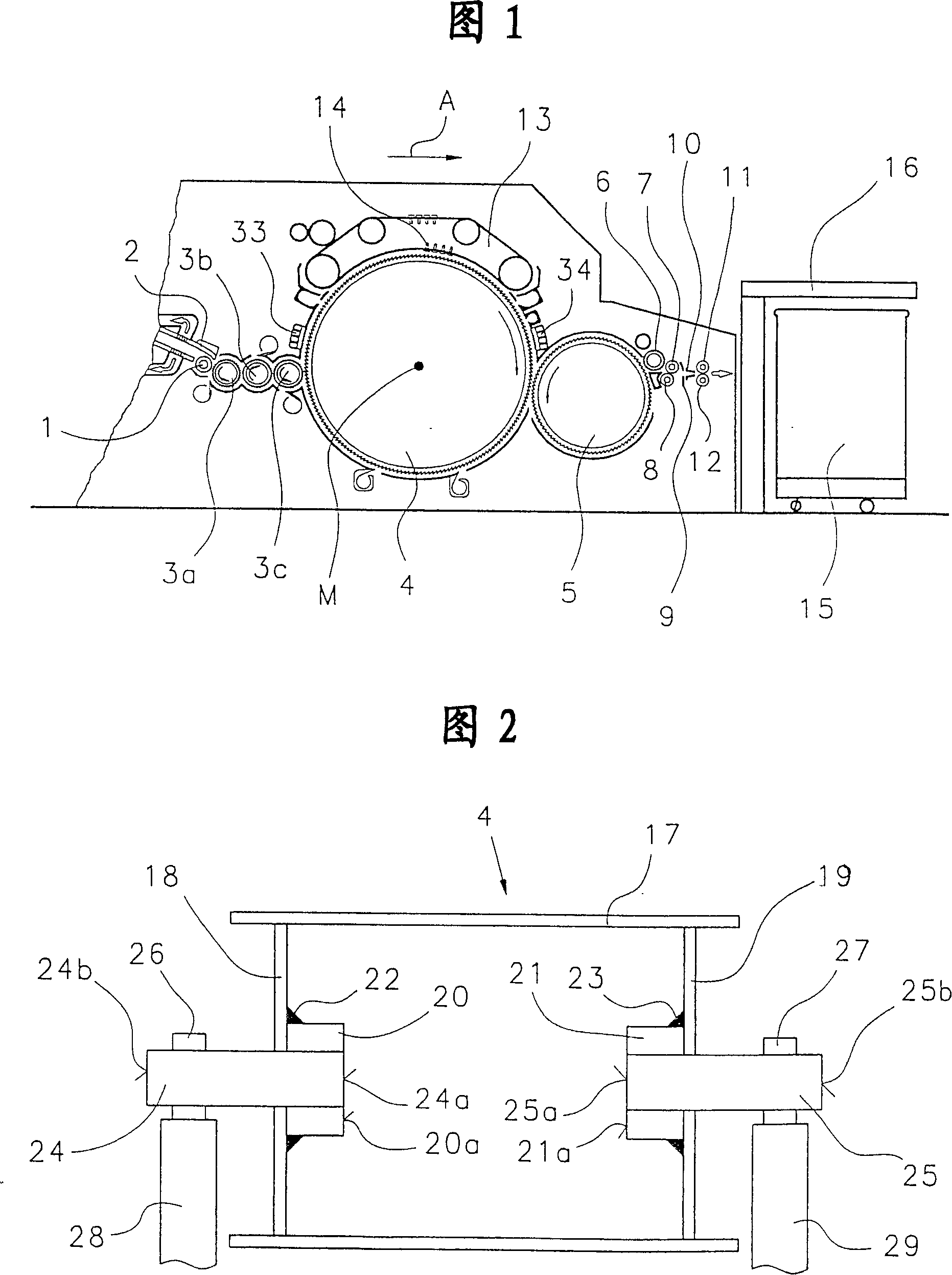
[0010] Fig. 1 represents a carding machine, for example Truetzschler-DK 903 high-efficiency carding machine, it has feed roller 1, curtain type feed table 2, licker-in roller 3a, 3b, 3c, carding cylinder 4, doffer cylinder 5, stripping roller 6 , crushing and cleaning rollers 7, 8, non-woven guide elements 9, condensate guides 10, traction rollers 11, 12, revolving flats 13 with flat rods 14 covering the card clothing, cans 15 and rings Bar device 16. The direction of rotation of the rollers is indicated by curved arrows. Use A to indicate the working direction.
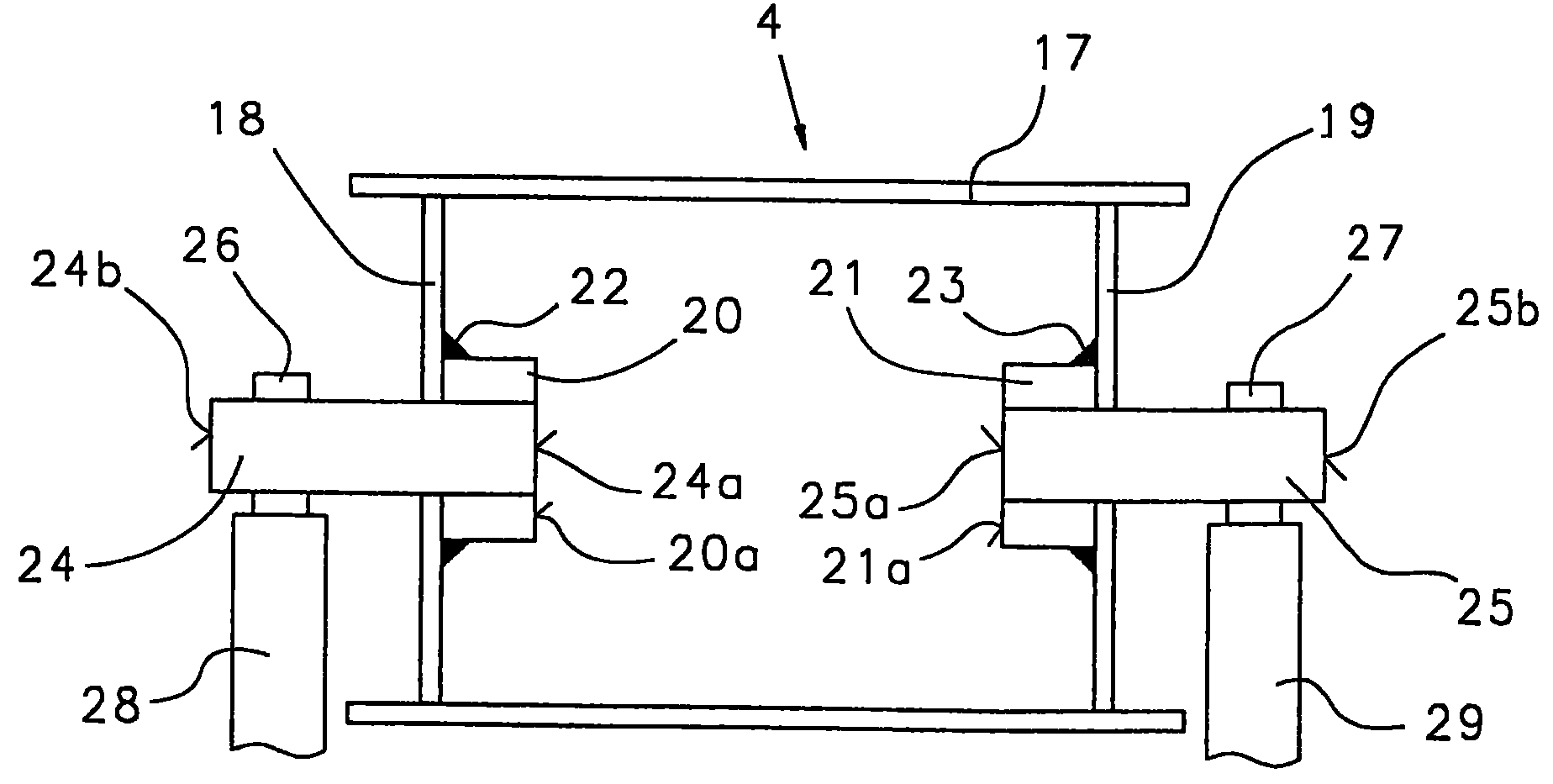
[0011] The drum 4 shown in FIG. 2 has a casing 17 made of sheet steel. The housing 17 is supported at its two ends on a substantially hollow cylindrical sleeve 20 or 21 (sleeve) across the drum bottoms 18 and 19 (disk) respectively. The sleeves 20, 21 are mounted on the drum bottom surfaces 18 and 19 by welding (22, 23). The sleeve 20 is fastened rotationally fixedly on a short cylindrical journal 24 by gluing, a...
PUM
 Abstract
Description
Claims
Application Information
 - R&D Engineer
- R&D Manager
- IP Professional
- Industry Leading Data Capabilities
- Powerful AI technology
- Patent DNA Extraction
Browse by: Latest US Patents, China's latest patents, Technical Efficacy Thesaurus, Application Domain, Technology Topic, Popular Technical Reports.
© 2024 PatSnap. All rights reserved.Legal|Privacy policy|Modern Slavery Act Transparency Statement|Sitemap|About US| Contact US: help@patsnap.com