
Gain controlling method for reversed distributed multipumping Raman amplifier

A Raman amplifier, gain adjustment technology, applied in instruments, wavelength division multiplexing systems, optics, etc., can solve the problems of cumbersome adjustment process, changing gain flatness, etc.

Inactive Publication Date: 2007-05-23
ZTE CORP
View PDF12 Cites 0 Cited by
  • Summary
  • Abstract
  • Description
  • Claims
  • Application Information

AI Technical Summary

Problems solved by technology

[0011] The technical problem to be solved by the present invention is to propose a method for adjusting the gain of a multi-pump reverse distributed Raman amplifier, which overcomes the difficulties of online configuration and gain adjustment of the multi-pump Raman amplifier, and manual online adjustment is easy to change the gain flatness and adjustment process. cumbersome question

Method used


Image

  • Gain controlling method for reversed distributed multipumping Raman amplifier
  • Gain controlling method for reversed distributed multipumping Raman amplifier
  • Gain controlling method for reversed distributed multipumping Raman amplifier

Examples


Embodiment Construction

[0031] The specific embodiment of the present invention is described in further detail below in conjunction with accompanying drawing:

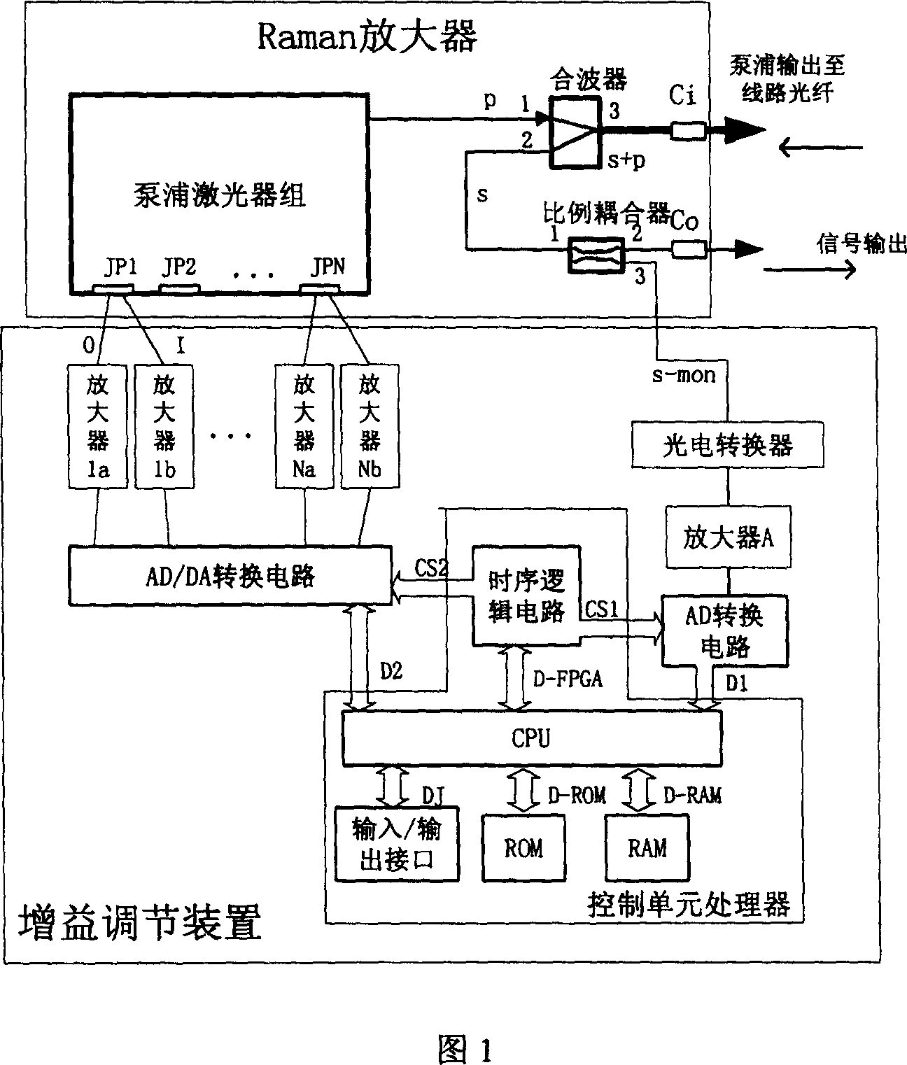
[0032]As shown in Figure 1, the multi-pump inverse Raman amplifier includes a pump laser group, a multiplexer and a proportional coupler. The optical power output by the pump laser group is output through the optical interface Ci after passing through the multiplexer. The amplified signal light is output from the multiplexer W. On the inner side of the signal light output optical interface Co, the signal optical power is collected by a proportional coupler. The detection quantity s-mon of the optical power of the output signal is obtained. The pump laser group is composed of N lasers, and all N lasers are connected to the gain adjustment device through electrical interfaces JP1, JP2, ..., JPN; the pump laser group can output laser radiation that meets the requirements during normal operation . The multiplexer forms a pump light path between...


PUM


Abstract

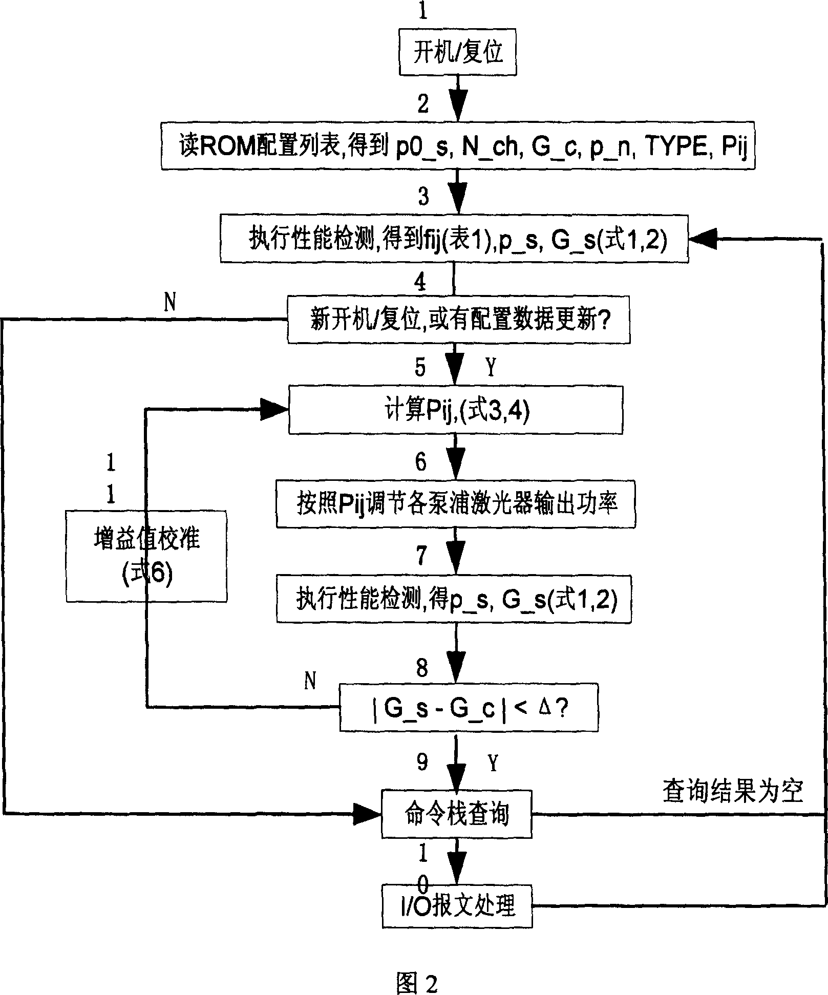
The method is as the follows. First, pumping power distribution value requiring gain is calculated according to gain requlation command, driving circuit of pumping laser is controlled by control unit processor according to new pumping power distributino value in order that the pumping laser can output the desired light power; then detection signal light power is compared with reference power to calculate current gain value; To compare gain valuve with gain disposal value for obtaining revised power distribution value of the pumping laser through recalculation according to its difference value and finally the pumping laser drive circuit is controlled by the control unit processor to enable the pumping laser to output the desired light power.

Description

technical field [0001] The invention relates to dense wavelength division multiplexing (DWDM) optical communication equipment in the field of optical communication, in particular to a gain adjustment method for a Raman (Raman) amplifier therein. Background technique [0002] In dense wavelength division multiplexing systems, in order to extend the transmission distance, optical amplifier devices are used, one of which is a Raman amplifier, which feeds high-power pump light into the optical fiber and utilizes the stimulated Raman scattering effect in the optical fiber (SRS effect), so that the energy of the pump light is transferred to the signal light longer than its wavelength, and the amplification of the signal light is realized. If the transmission fiber is directly used as the amplification medium, this kind of Raman amplifier is a distributed Raman amplifier. The Raman amplifier has a wide range of action and is more suitable for wavelength division multiplexing optic...

Claims


Application Information

Patent Timeline
Patent Type & Authority Patents(China)
IPC IPC(8): G02F1/39H04J14/02
Inventor 王加莹
Owner ZTE CORP
Learn More